Goal of the Project
For the past few months, Turkey has been really hot, and air conditioners and fans seem to be the only way to overcome this extreme heat. However, as everyone continues to power more of these devices, a great amount of energy is being lost. As IEA - whose mission has expanded in recent years to emphasize the promotion of renewable energy sources - states in this article, "the growing use of air conditioners in homes and offices around the world will be one of the top drivers of global electricity demand over the next three decades, according to new analysis. Using air conditioners and electric fans to stay cool already accounts for about a fifth of the total electricity used in buildings around the world – or 10% of all global electricity consumption today".
"Global energy demand from air conditioners is expected to triple by 2050, requiring new electricity capacity the equivalent to the combined electricity capacity of the United States, the EU and Japan today. The global stock of air conditioners in buildings will grow to 5.6 billion by 2050, up from 1.6 billion today – which amounts to 10 new ACs sold every second for the next 30 years". While the main objective to overcome this problem is to dramatically increase the efficiency of air conditioners, I started to think if it would be possible to save some of the wasted energy via an external device.
Since almost all air conditioners have an AC fan unit, I got the idea of using the air that comes out of these units. A wind turbine should be able to use the air coming out of these units to genereate electricity. This would allow people to save at least a portion of the wasted energy. However, for this to work, a miniature wind turbine would be required to create a portable wind turbine that can be placed near the AC Fan units.
After doing a lot of research on the types of wind turbines, I came to the conclusion that a Savonius Wind Turbine would be the best choice for this project. I believe that this idea could help save a lot of energy if used properly. In addition, this wind turbine could be used to get several data (amount of energy generated from AC Fan units, the usage of ACs throughout the year and its distribution, weather conditions throughout the year that might affect the energy generated, etc.) for further research.
Research
To get an effective result from this project, I had to do a lot of research. From learning how AC units function, to figuring out what aspects of the savonuis wind turbine I should be most careful with. The following are the main researches and papers that helped me throughout my research:
Performance and Flow Field Evaluation of a Savonius Rotor Tested in a Wind Tunnel
How to calculate rpm and power output of Savonius Turbine
A review on the performance of Savonius wind turbines
Wind power plant from air conditioning exhaust using L Savonius wind turbine
Optimal blade shape of a modified Savonius turbine using an obstacle shielding the returning blade
Optimal design of a Savonius turbine
Blade shape optimization of the Savonius wind turbine using a genetic algorithm
Comparison of Various Blade Profiles in a Two-Blade Conventional Savonius Wind Turbine
Review of savonius wind turbine design and performance
Numerical investigation of conventional and modified Savonius wind turbines
Preliminary study and development of prototype of Savonius wind turbine
Designing the Wind Turbine Prototypes
We had learned how to use Fusion 360 in Week 2, so I decided to continue working on Fusion for the design of my savonius wind turbine. After my research, I came across several different designs which utilized different blade structures. First of all, I wanted to start designing basic prototypes for these blade formations. I designed six different prototypes.
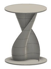
The first one had a single blade that would be curved both ways. I used the "Form" section in Fusion 360 in order to obtain the shape of this blade. For the next one, I used two semi-circle blades instead of a single blade formation that would curve in all directions. While designing this prototype and the following ones, I used basic sketches and extruded them to obtain the required shapes. For my third design, I experimented with a different blade shape to see how a larger blade (almost looks like an elipse) would fit into the design.
The following prototypes were based on the second design that I made. These have the same blade shape and formation; however I decided to alter the number of blades used in the wind turbine. For designs 4, 5 & 6 I used three blades, four blades, and finally five blades respectivelly. Since the images I came across on the inetrent were mainly 2D sketches or from limited angles, these helped me to get a better understanding of each blade design.
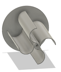
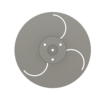
After some further research, I decided that using the fourth design where I utilized three semi-circle blades would create the most efficient results. Due to its shape, this design allowed the wind (air from the AC fan unit in my case) to be gathered inside the blade, so that the turbine rotates more easily. With this being the most effective blade shape, I came to the conclusion that three blades would be enough for a minature savonuis wind turbine since I wanted to keep it light. Now, I need to work on a more professional design based on this prototype. You can see all the prototypes in order on the right.
Download Prototype 1
Download Prototype 2
Download Prototype 3
Download Prototype 4
Download Prototype 5
Download Prototype 6
Making The First Proper Design
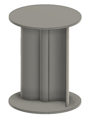
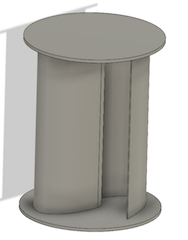
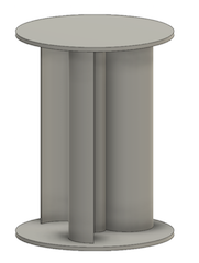
Now that I knew what type of Savonius Wind Turbine I wanted to build, I could start working on a more proffesional design. While I was able to get the overall shape of the wind turbine in Prototype 4, this design could not be used in real life. I needed something that I can really assemble, and use in real life. After going through some different wind turbines, I figured out a way to assemble everything together.
I decided to go with a design where the whole structure would rotate instead of just the blades. I was going to use a "guide plate" to fit the blades into; this component would keep the blades in place while the whole system rotated. An additional component that I called the "lid piece" would be attached to both ends to make sure that none of the blades slipped out of their place while rotating. I would place a shaft through the wind turbine to connect everything together.
So I got to work. Our assignment for Week 6 was to design and prepare to print a component we need for our final project or a small object that could not be (easily) made by subtractive methods. For Week 6, I decided to work on my first design for the wind turbine. You can follow all of the design process on my Week 6 page, and the final results are attached below as well.
You can download this design here
Working on the Final 3D Design
The Sketch
There aren't any fablabs near me that I could get acces to, and I don't have a 3D printer. However, to get a proper result, I needed to 3D print several components of the wind turbine. After asking for help from everyone I knew, a friend of mine allowed me to use her 3D printer. After learning the details of her 3D printer, I realized that the size limits of the 3D printer was way smaller than my initial design. I needed a smaller wind turbine for it to be printed, and this would also be useful for me since the design would be lighter.
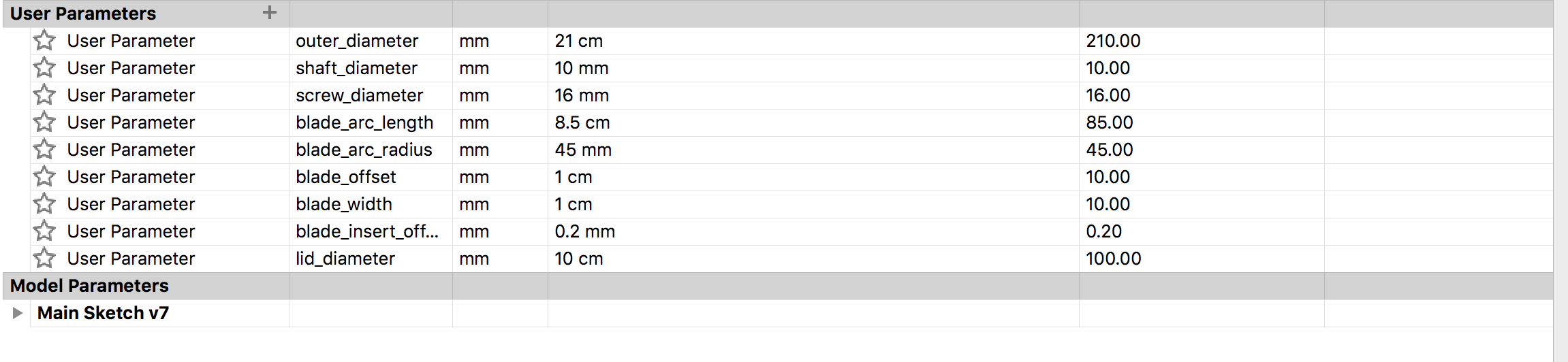
Although the overall design was just as I wanted it to be, I had to change the dimensions. I also realized that I made this first design in a single file; this could be a problem for individually printing the components. I had used detailed paramters in my first design to be able to change any dimesion later on. However, since I also needed to seperate the components, I figured out that starting over would be the best choice.
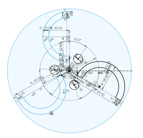
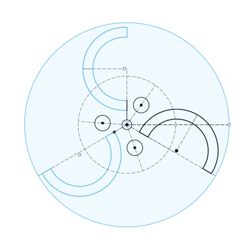
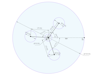
I basically followed the same process that I went through in the Week 6 design. I sketched a circle within the size limits of my friend's 3D printer. I measured the dimensions of the holes and their placements in the previous design. I recorded these values, and used them to sketch the circles for the holes on my new design. There was no problem with the middle (shaft) hole, but I needed to move the screw holes since the outer circle has gotten smaller. I arranged the placement of these screw holes in a way that would allow me to attach the blades as well.
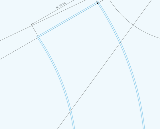
Just like last time, I used parameters for every important dimension so that I can alter these values later on if I need to. Now that all the holes were done, I needed to sketch the shape of the blades. I had to change the size of the blades as well to get them to fit inside the new size limits. I used a three point arc tool to get the shape of these blades, and recorded everything on the parameters. I made sure that I used the right directions for the blades this time since I had a lot of trouble with that in the previous model.
Before finishing the sketch, I decided to add the rquired offsets - I decided to these at the beginning this time since it gets harder to do after creating all the components. I added a 0.2mm offset to the blade holes just like last time. The purpose of this was to make sure that the the printed pieces would be able to fit inside their respective holes in real life. This time, I added a small offset for the screw and shaft holes as well, so that I can easily attach all the components together after printing the pieces. Finally I added another circle in the middle that would represent the lid piece.
Creating The Components
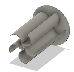
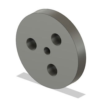
Now that the sketch was completed, I could start creating the components. This time, I needed them in seperate files so that I can properly print them later on. For this purpose, I saved my sketch, and exported it into a new design. In this new design, I chose the circle that represented the lid, and extruded it to the required width. I used parameters for all of the extrusions as well. After creating the lid, I opened a new design and once again inserted the main sketch in it. This time I only extruded the Guide Plate while making sure that I was selecting the ofsetted lines. Finally, I inserted my sketch into another design, and extruded one blade, making sure that it fits the size limits of the 3D printer. At last, I had all of the required components in seperate files, and they were all designed according to the size restrictions of the printer.
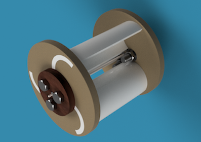
I opened a new design, and inserted all of these components inside it. I used this file to build the whole assembly. I first placed the lid on top of the Guide Plate. Using the m16 bolt from my previous design, I connected the two components together with rigid joints. However, since I decreased the size of my design, I had a hard time getting the screws to fit. I decided to cut a section of the washers, and everything worked perfectly afterwards. I followed the same process to connect the Guide Plate & Lid for the other end of the wind turbine. Then, I inserted three copies of the blade that I created. I attached each blade inside their respective holes via slider joints. The wind turbine was now assembled.
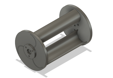
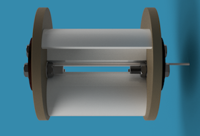
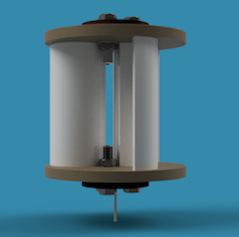
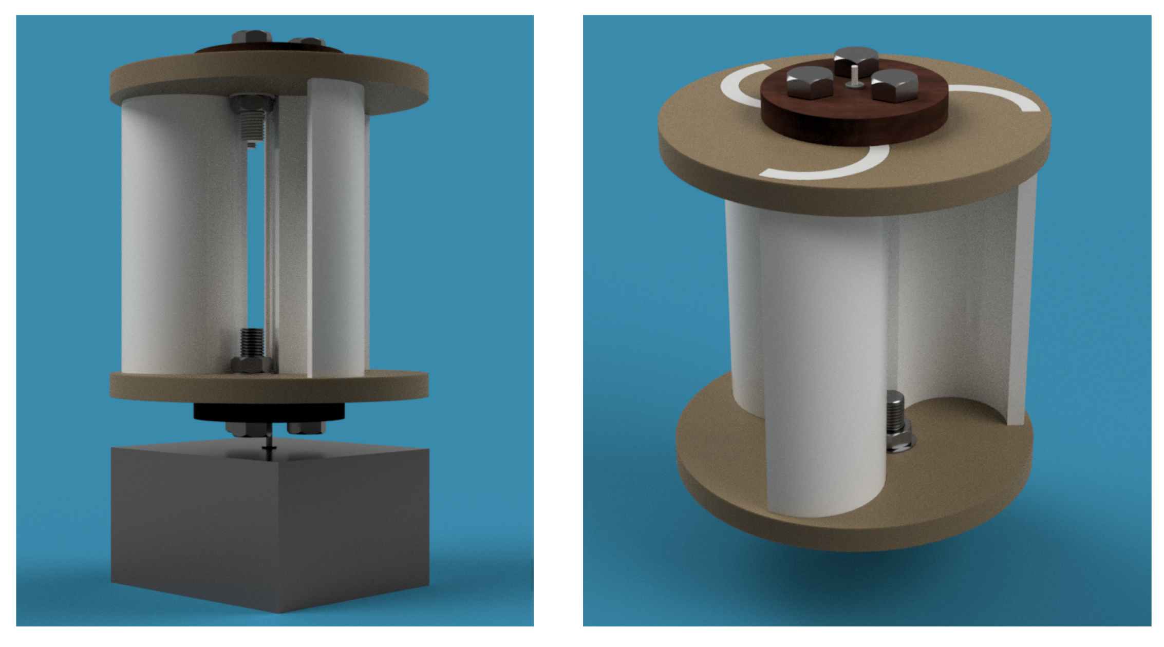
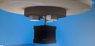
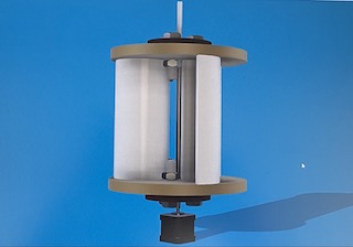
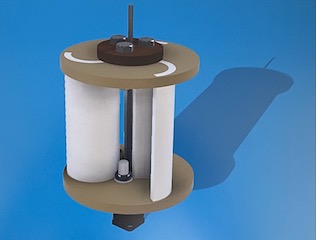
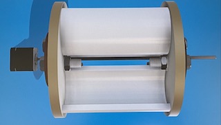
I created a shaft, and a symbolic box to have something that the wind turbine could be placed on. I connected the shaft to the wind turbine with a rigid joint, and then connected the shaft's other end to the box using a revolute joint. This would allow the whole assembly to rotate together. Finally, I arranged the materials of the components so that they could be easily told apart. I also played around with the background & lighting, and used Fusion 360's Rendering section to get some final images.
Download the Blade
Download the Guide Plate
Download the Lid
Figuring Out the Electrical Aspects
After completing the design of my savonius wind turbine, I needed to figure out how the electrical components would function. I wanted to store the electricity generated from the wind turbine. For this, I needed a kind of motor, and probbaly a battery that could store this electricity. I had a 12V battery, but it seemed like a bit much for this miniature wind turbine. Hence, I started doing some more research to see how other people approached similar problems. I finally came across a proper project tutorial. The project was made by Adrian Cubas, and he was using a Stepper Motor to generate the electricity. Since we learned how to use Stepper Motors in class, I thought that this would be a great option. I went through the electrical wiring as well, and decided to follow the lead of this project to build a proper circuit for my own design.
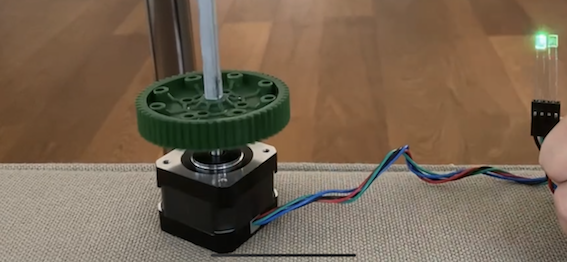
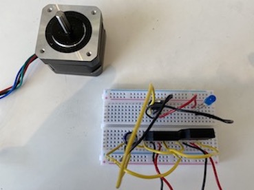
The first thing that I wanted to do was to see if the Steper Motor really generated electricity. To demonstrate this, I took a LED, and attached its legs to the two connected wires of the stepper motor (I had figured out which cables are connected via a multimeter in class). I started to rotate the Stepper Motor's shaft by hand, and saw the LED momentarily light up. To get more appropriate results, I needed the shaft to be rotated continously. To do this more easily, I used the piece that I had built for Week 10. I had drilled a piece so that it would fit the Stepper Motor. However, this time I used a gear instead of a wheel, and attached a longer shaft to the other end of the gear. By doing so, I was able to connect the shaft to the Stepper Motor. By rotating this shaft, I could easily get a more continous result.
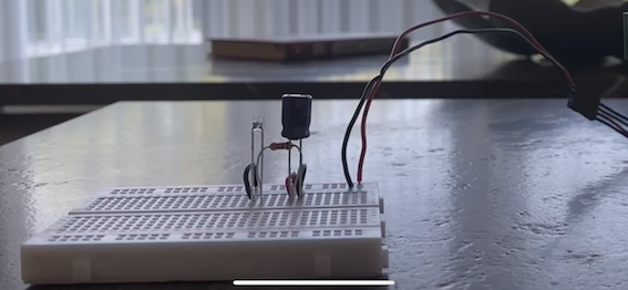
After playing around with the Stepper Motor and the LEDs for a while, I accidently burned one of the LEDs. There was going to be electrical components in my final design to prevent this, but I wanted to create a solution just for now. I built a basic circuit which included a capacitor, and a 470Ω resistor to prevent the Led from burning due to the sudden current provided by the Stepper Motor. I used this circuit to light up the LED again, and it worked perfectly. The light was much more dimmer due to the resistor that placed in front of it, but it was a temporary solution anyways. Seeing that this was working as desired, I concluded that the Stepper Motor would be the best choice for my project.
Fixing the 3D Design
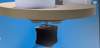
After deciding to use a Stepper Motor for my Savonius Wind Turbine, I needed to slightly change my design so that it would be connectable to the Stepper Motor. In my previous design I had used a symbolic box that the wind turbine would be fixed on. I deleted that bottom component to change it with a Stepper Motor. From grabcad, I downloaded a Stepper Motor design, and inserted it inside my assembly file. This motor would be the base of my wind turbine.
The problem was that the shaft hole in the middle of the lid & Guide Plate was not made according to the Stepper Motor. I didn't want to change all of the holes' sizes since I would need to attach a different shaft through the upper section of the Wind Turbine. Hence, I decided to design a "coupler" that would connect these shafts. I sketched a circle larger than the hole, and extruded it; this was going to be the section that would hold the coupler in place. On one side of this circular piece, I extruded a new circle which was slightly smaller than the hole itself. This piece would fit inside the hole. I had a 3D design of the shaft that I was previously using to rotate the motor. So I inserted the shaft's design, and used the combine/cut command to create a hole at the same size of the shaft. Using the same method, I created a new circular body on the other side and made a hole inside it via the Stepper Motor that I downloaded. This coupler design would allow me to attach one shaft from one side, and the Stepper Motor's shaft from the other end, while fixing these structures inside the initial hole on the Guide Plate / Lid. I now needed to erase the Stepper Motor and the shaft from the file, so that I could print the coupler. However, since I had used these components in my design, Fusion 360 gave several errors that prevented me from downloading the STL file. I measured every single side on the coupler and recorded these values. Using these measurements, I sketched & extruded a whole new coupler. Since I didn't use the other components for this one, I was able to download its file now.
I also needed a different coupler for the upper part of the wind turbine, just to hold the other shaft in place. This was a lot more simple; I once again created a circle that was a bit bigger than the hole. I created a new sketch on this circle, and sketched the shape of the shaft I was using based on. the values I just recorded for the previous one. I extruded all the sketches, and I now had the piece that would fix the shaft inside the larger holes.
I inserted these couplers inside my assembly folder, and attached them to their respective holes via rigid joints. Then, I attached the new shaft inside the holes, and attached the Stepper Motor to the coupler at the bottom. Everything seemed to be right now, and I managed to alter my Savonius Wind Turbine design so that I can connect it to the Stepper Motor.
Download the Stepper Coupler
Download the Shaft Coupler
Manufacturing the Components
Laser Cutting
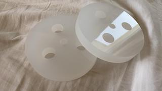
With all of the designs completed, I could now begin to really manufacture the components. I already knew that I wanted to 3D print several components such as the blades and the Guide PLate so that they would be sturdy and light. Nevertheless, as I was planning the manufacturing process, I remembered that we talked about laser cutting in Week 2. Even though I made 2D designs before, I had never used laser cutting before and really wanted to try it out. I managed to reach out to a nearby company that had acces to CNC machines, and also cut personal orders. (It was a small company and didn't have a website so I didn't attach a link here). I decided to get the Lid pieces cut out via a CNC machine so that they can be more robust and carry the screws.
I went back to my original sketch, and copied it into a new file. I deleted all of the unnecessary sections of the sketch and only kept the ones required for the Lid. I needed to simplify the sketch to send it to the company. I pasted the dimensions on top of the sketch in Fusion 360 so that it would be easier to read. I also rendered a few images of the Lid piece so that it can help them better understand what I was trying to accomplish.
I decided to use PVC (with a width of 1.5cm) so that I could obtain a light but strong component. I sent all of the files to them, and got back the pieces in perfect shape. I was really happy with the results.
3D Printing
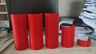
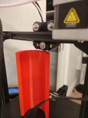
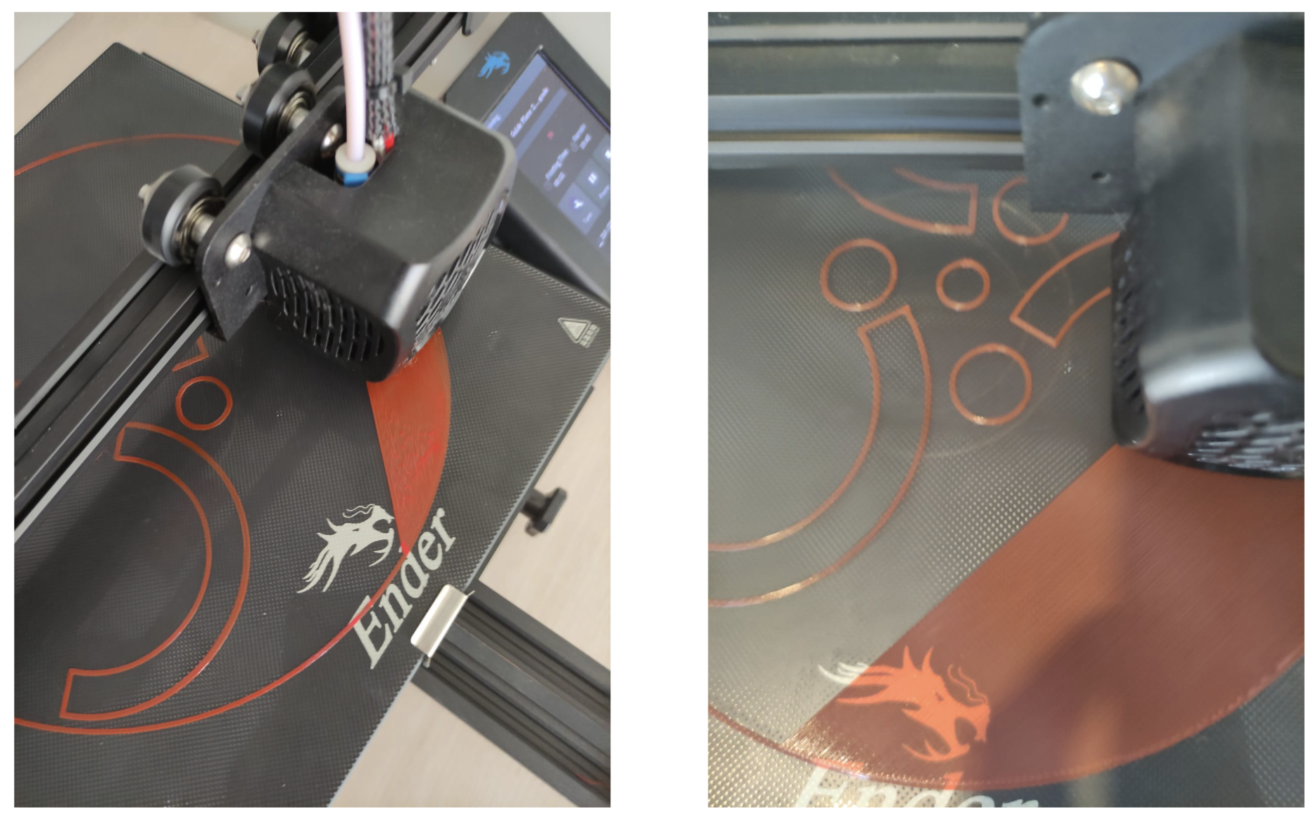
After getting the Lid pieces cut with a CNC machine, I needed to 3D print the remaining components. Using my friend's 3D printer, I started to print the blades. However, the printer kept messing up, and the first few tries did not really work. The printer slightly slipped at some points for some reason and messed up the component, so I had to stop those printing procedures. I needed to alter some of the settings on the printer, and followed the printing process as much as I could to make sure that everything was going according to the plan. After a lot of failed attempts, I managed to print the three blades.
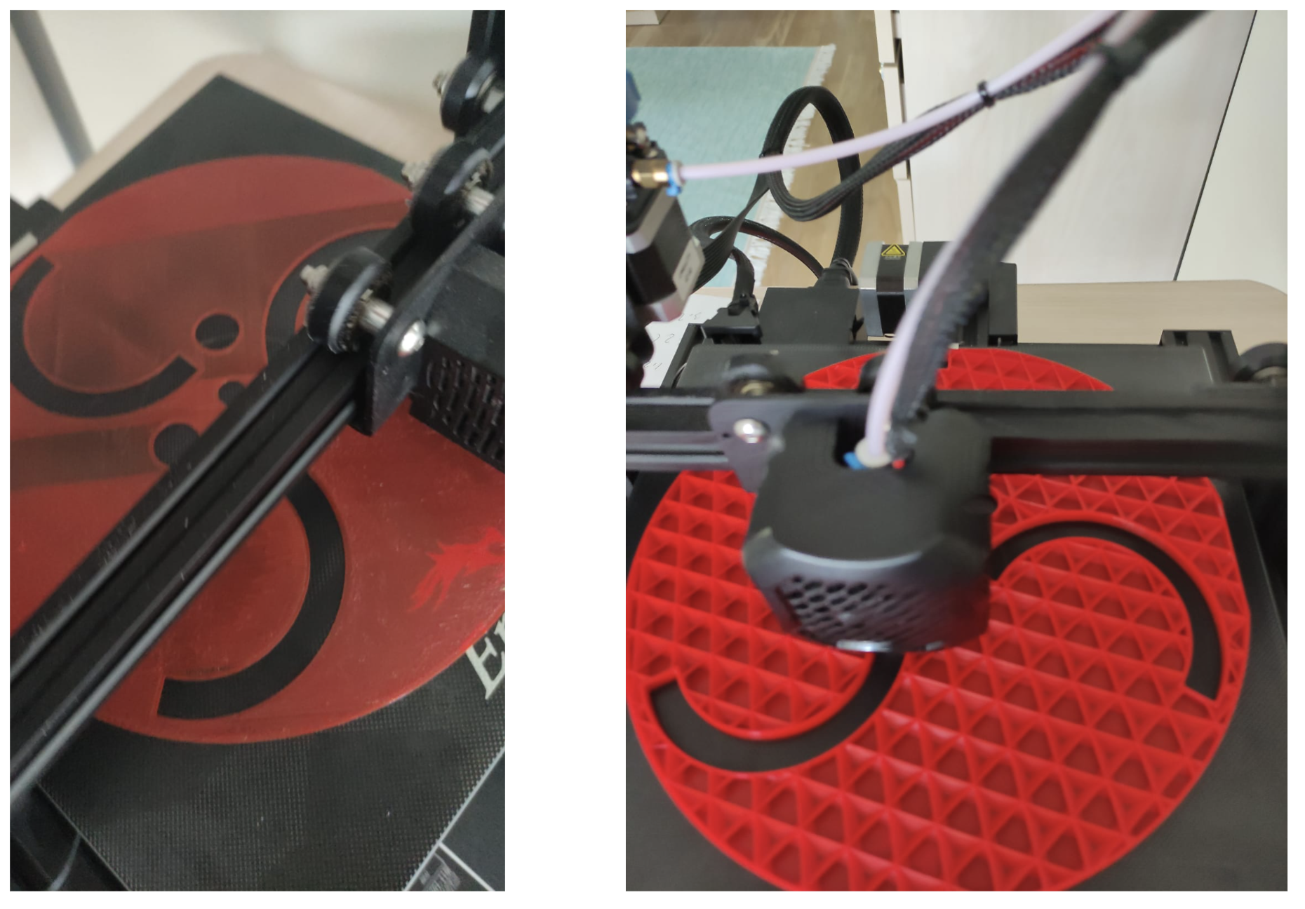
Now I needed to print the Guide Plates. I had better luck with the first guide plate. I once again had to play around with some of the settings on the printer to get the right results, and printed the Guide Plates. I thought that the Guide Plates were a bit too thick. Therefore, I didn't wait the full time for the second Guide Plate (the one that would be on the top), and got a thinner guide plate. I didn't want the wind turbine to be too heavy, so I was satisfied with these results.
I finally printed the couplers. I decided to print these in a horizontal placement so that they can handle more stress. I didn't have any problems with these final pieces, and quickly printed all of the required couplers. I now had all of the required components to build my Savonious Wind Turbine.

Building the Circuit
After all of the components were manufactured, I could begin to work on the circuit that I need to get this savonius wind turbine to work. I followed the project tutorial that I mentioned before to correctly build the required circuit. I needed some components that I didn't have, so I quickly ordered those.
The first piece that I ordered was a 5V Voltage Regulator which is a three-terminal positive regulator with a 5V fixed output voltage. This fixed regulator provides a local regulation, internal current limiting, thermal shut-down control, and safe area protection for the project. Since the voltage supplied by the wind turbine would not be the same at all times, I needed this component to supply a fixed voltage to make sure that I did not damage anything.
The second component that I ordered was a Diode Bridge Rectifier. Bridge rectifiers are discrete semiconductors that convert an input AC current into a DC current as an output. Bridge rectifiers feature four diodes in a bridge configuration that provides the same polarity of output voltage for either polarity of input voltage. The ones that I got were for 4 Amps.
And the last component that I ordered was a USB Female Connector. This would allow me to connect a USB to the end of my circuit to draw the power that the savonius wind turbine generates. I could also use these to connect my circuit to a microcontroller in order to power it. Hencei this was a crucial component that would allow me to transfer the genereated voltage.
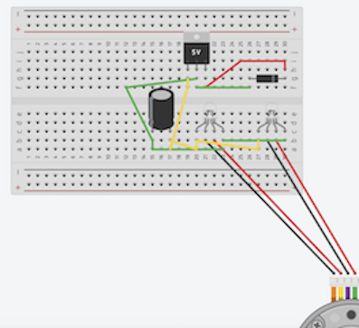
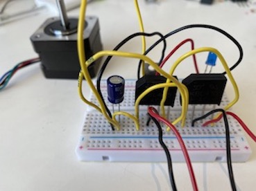
When the 5V Voltage Regulators and the Diode Bridge Rectifiers arrived, I began to build the circuit. There was an image on the tutorial that displayed how each component should be connected to one another. However, I was planning on building the circuit on a Breadboard, and therefore decided to use Tinkercad before really building the circuit. I designed my circuit on Tinkercad, but had to use some different components (with same number of pins) instead of certain components that I couldn't find in the Tinkercad library. I used a RGB LED to represent the Diode Bridge Rectifier. Instead of a Stepper Motor, I had to use a DC Motor with Encoder, and used only four of its cables. Finally, I used diode to represent the Female USB Connector. Even though I had to many different components in this design, it gave me a better idea of how to wire my circuit on a Breadboard.
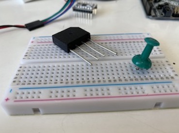
I built my circuit, and everything seemed to be connected right. One problem that I had while building the circuit was with the Diode Bridge Rectifiers. These components were not designed according to a Breadboard, and therefore its legs would not fit into the hoples of the Breadboard. I had to use a pushpin to enlarge these holes so that the Diode Bridge Rectifier would fit inside. The pushpin method worked, and I was able to fully connect my circuit. However, the USB Female Connectors that I ordered were running late, and I didn't have any way of transferring the power drawn from the wind turbine. I couldn't take the risk of just waiting for the USB Female Connectors to arrive, so I had to come up with a different solution. After going through all the materials in the kit, I finally came up with an idea.
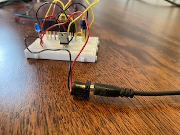
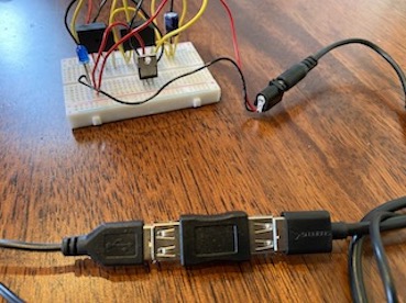
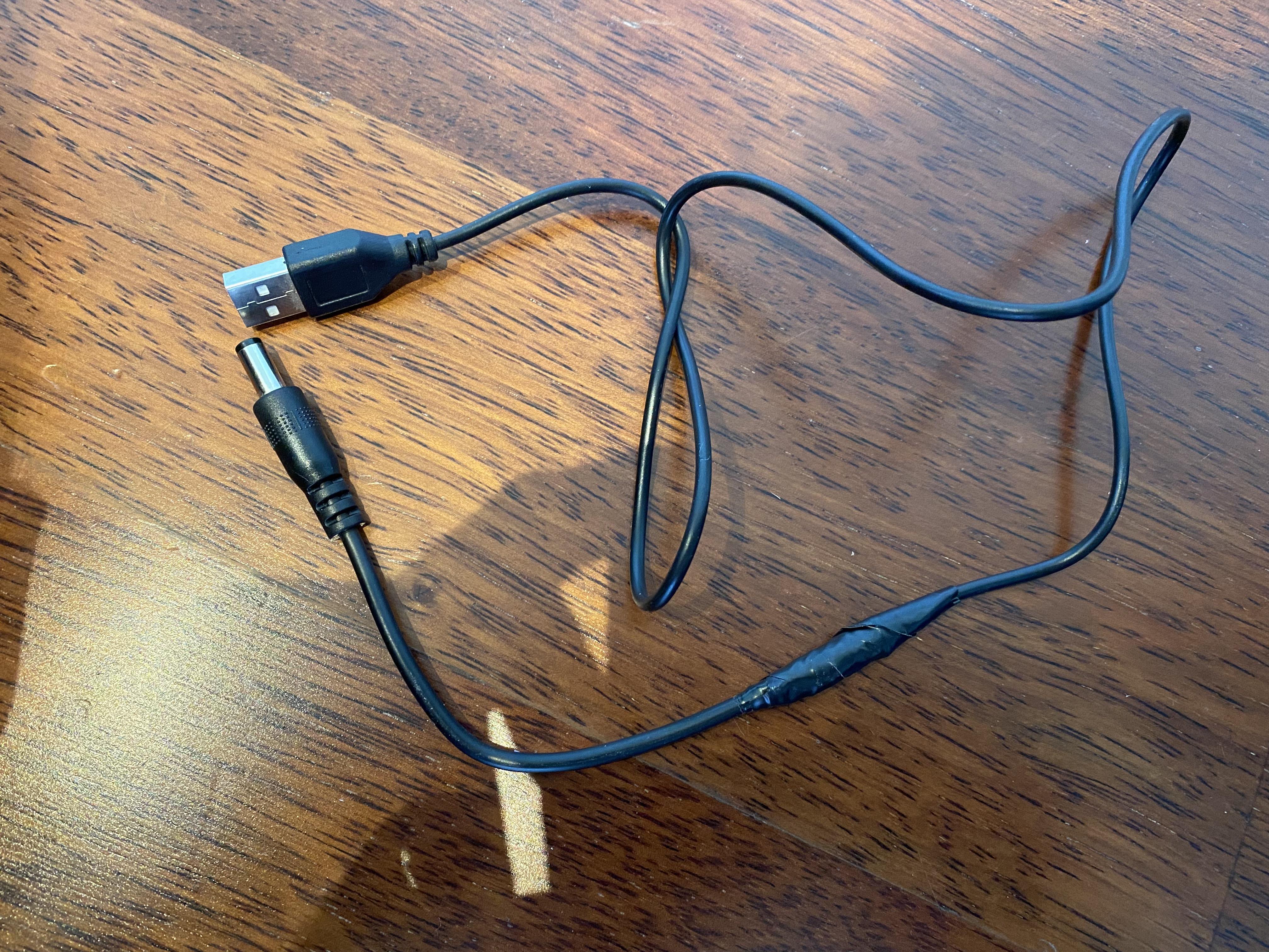
I got the DC female connector / input from the battery pack that we had, and connected it to where I was going to attach the USB Female Connector. Now, I needed a DC to USB cable so that I can attach this to another device. I went to a lot of stores that sold electric components but none of them had a USB to DC cable that would fit to the component that I had. I didn't have enough time to order one, so I had to figure something out. Eventually, I went to a local electrician, and asked for their help to connect two cables. I found one USB cable and a DC cable. I cut these cables with a wire stripper, and connected the two together with the help of the electrician. We then covered this opening with some tape so that it would be safer. After assembling this new cable, I needed to transfer this to a USB input. Therefore, I found and bought a double female USB connector (which is a component that has USB Female Connectors on both ends). This component wouldn't have worked with my original design, but I could attach it to the end of my new cable. Now that the other end of this component was empty, I had a USB Female Connector that is connected to the end of my circuit. I tried to power this circuit with a blue LED just to see if it was working. Everything seemed to function correctly, and I decided to keep the LED on the circuit so that I can tell when it's really working.
I finally used the multimeter to measure some values. I spinned the Stepper Motor with a drill to get a continous current from the motor. While the motor was rotating, I measured the values from the end of the circuit (where I connected the DC Female Connector). I read approximately 3.6V to 4V, and 120 mA at this point. These were reasonable values that I could work with. Thus, my circuit was also completed, and I could begin to assemble the Savonius Wind Turbine to connect it to my Stepper Motor.
Assembly of the Wind Turbine
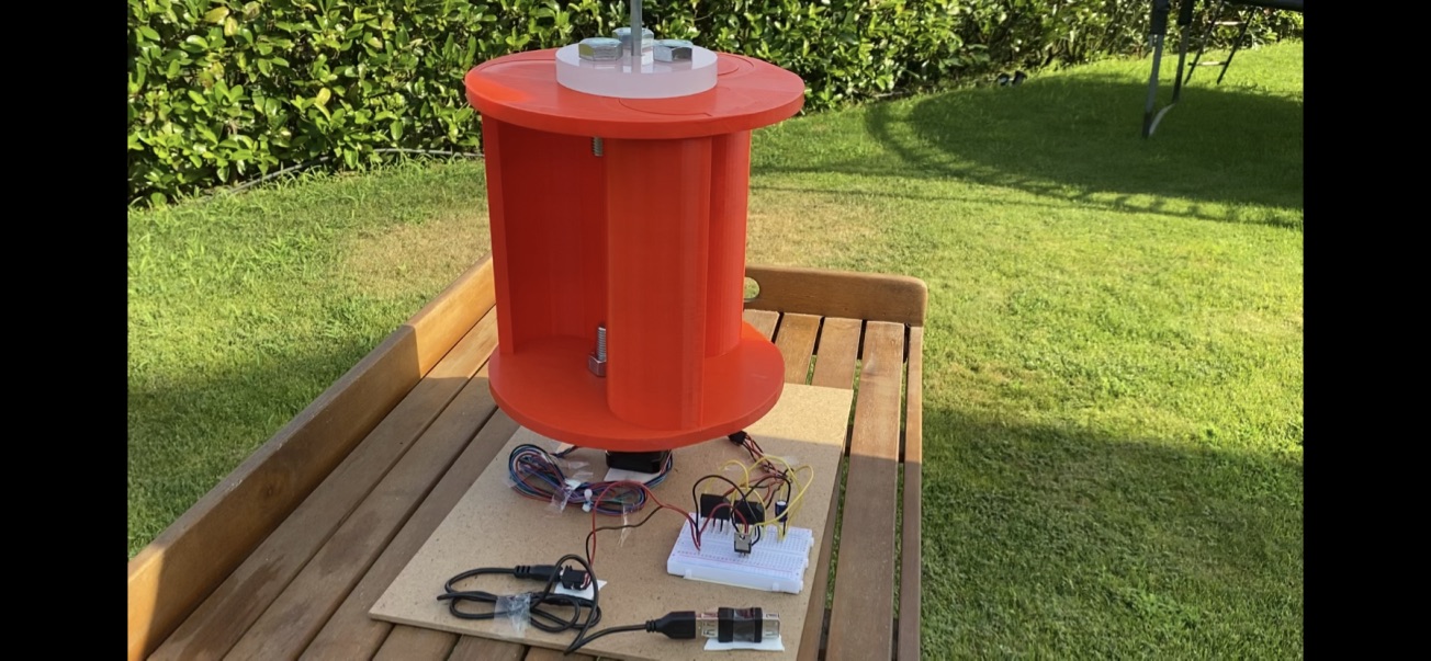
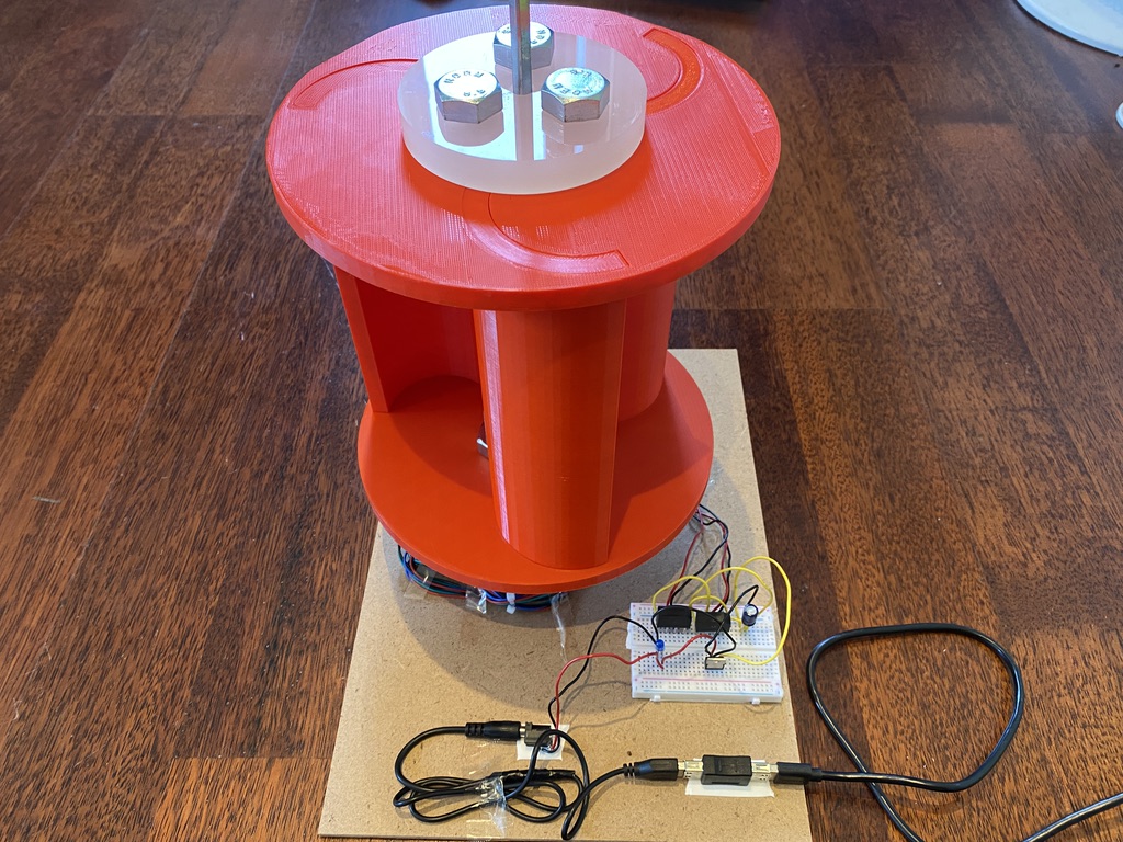
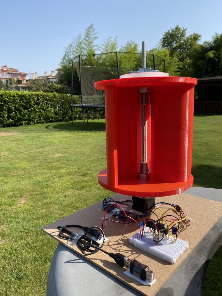
All of the components were manufactured, and I had finished the circuit as well. Now, it was time to begin the assembly of the wind turbine. I placed the blades inside the Guide plates. I had to force them in a little bit, but all of them fit into their respective holes perfectly. Afterwards, I placed the Lid component on top, and attached it to the Guid Plate with the use of the m16 screws that I ordered. I decided that I didn't need the washers for the final product, so I didn't need to cut them in real life. I took off the support pieces from the couplers, and inserted them in their holes. I had to force them a little bit just like the blades, but everything was working in the end. The mechanical aspect of my project was completed, and I just needed to connect it with the circuit.
I took a thick cardboard, and sticked all of the elevctrical components on it (such as the Stepper Motor, the Breadboard, etc.). I inserted the other end of the coupler on the Stepper Motor's shaft, and made sure that it was stable on there. Then, I placed the other long shaft from the top, so that it can hold everything better together. I tried rotating the Wind Turbine, and saw that the blue LED on my circuit was lighting up. This meant that everything was functioning as it should.
For my demonstrations, I did three main experiments which are also displayed on my Youtube video. First of all, I charged a power bank via the Savonius Wind Turbine. However, there was very little wind that day, and the Wind Turbine needed to rotate really fast to be able to supply the requiered power. To make sure that everything was working, I used a device similar to a leaf-blower to continously rotate the wind turbine. I connected the Power Bank to the USB female connector, and began to rotate the wind turbine. After waiting for a few seconds, the Savonius Wind Turbine started to charge the power bank just as I planned.
The next step was to charge a phone using the wind turbine. I learned that the Power Bank could be charging something and be charged at the same time. So, I connected a charging cable to the Powerbank which was connected to the wind Turbine. Even though there was a little delay since the wind turbine is generating a small voltage output, the Savonius Wind Turbine was able to charge the phone as well.
Finally, I wanted to use some other things that we learned in class with my project. I wasn't able to do any coding with this project, so I decided to run a code that previosly wrote while powering the Metro Board from the Wind Turbine. First, I downloaded an example LED strip code to see if it would work, and downloaded it to my Metro Board from my computer (This code is attached below). Then, I attached the Metro Board's cable to the Wind Turbine's USB Female Connector. I was able to generate the required power and light up a LED strip just by using my Savanious Wind Turbine. Afterwards, I rebuilt their required circuits and powered the codes that I wrote in Week 3, Week 5, Week 7, and Week 8. They all functioned perfectly with the Savanious Wind Turbine. You can go to each week's page to see these codes.
My project is officially completyed and it was able to do everything that I wanted. I have further plans to improve this design. The main things that I have in mind right now are making a lighter design, figuring out a way to decrease the friction between the Stepper Motor and the Wind Turbine so that it can rotate more freely, and powering more sensors with the Wind Turbine. In my inital project idea, I had mentioned colelcting further data from this Savanious Wind Turbine. For this purpose, I plan on connecting the thermistor to my circuit just like I did in Week 7. This would allow me to track how much power can be generated with the wind turbine in different weather conditions, and make some new analysis. I would also like to figure out a way for the Wind Turbine to display exactly how much energy it has saved, so that it would be more beneficial to the users, and open whole new doors for some research. Nevertheless, even though there are certain aspects of my design that I would like to improve, I'm really happy with the final result, and feel like I got to display most of the skills that I learned in this class.