ASSIGNMENTS
1. Program a microcontroller to produce an output using at least one button for input. Include a conditional statement and a for() loop.
2. Think about your final project and any additional components you might want. Start working on the 3D design for your project, especially components you might want to be lasercut or 3D printed. We can't make any promises, but we will do our best to accommodate requests within reason. Next Tuesday the 13th is the deadline for requests, in order for us to print/cut, mail, and get to you in time for you to assemble your project. (This will also be your assignment for next class). Please feel free to send us your designs prior to that for feedback. Please also feel free to use models from this collection of 3D models of kit components, or from other online collections like grabcad.com or Thingiverse.
My Work
After trying out and learning how to use several different loop functions in Arduino, it was time to think of an idea for the assignment. I wanted to try and use a component that I hadn't used yet to try something new. After going through the kit, I cam across the RGB LEDs. I decided to build a circuit that would utilize the RGB LED and some buttons. For this purpose, I started to do some research to see if anyone had built a similar circuit. I went through several websites and finally found a design that I liked. The guide that I decided to follow is Step 3 from this website.
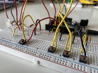
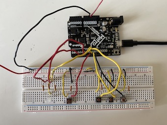
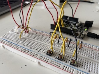
Using the Tinkercad design from the website, I started to build my own circuit. I had to cut a few new wires, and managed to fully build the circuit. I had to add a few more cables that weren't shown on the Tinkercad design to make sure that everything was connected on my breadboard. I uploaded the code from the website; however, nothing was working. The RGB Led was shining green, and it would turn off when I pressed the third button. The first and second buttons were not working at all. Hence, none of the buttons were working as they were supposed to. I had no idea why, and started try different things to fix this issue.
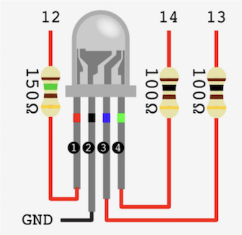
I changed some of the wires with more clean and unbent ones, but it didn't work. Then I tried changing some of the buttons to see if there was a problem with them, but I quickly saw that the problem was not related to the buttons at all. I also tried to change the ports that I was using, but that didn't work as well. The only other idea that I had was to change to Arduino code. So, I started to play around with the code that I downloaded, and changed several aspects of the code. None of the changes that I made worked, and the RGB was still not working as I desired. I didn't know what else I could do, so I started to research how RGB LEDs worked, and how other people built their circuits using the RGB LED. After a while, I came across the image that I attached to the left. I realized that the long leg of the RGB LED was supposed to be connected to the ground. However, on the Tinkercad model from the aforementioned website, the long leg was connected to the power source (+ terminal on the breadboard). I changed the wiring of the RGB LED, and restarted the Metro Board. Everything was working now, and I was able to control the color of the RGB LED via the three buttons that I attached.
The code that I used for this project is also below. It is a quite simple code which utilizes if/else statements for each button. I really liked the outcome of this assignment.
FOR Loop
For this assignment I also needed to work with a for() loop. Since I had already started working with the RGB LED, I wanted to implement the for() loop inside this circuit design. I researched a little bit for a for() loop that powers an RGB LED. I came across a video that demonstrates how loops are used to power RGB LEDs. I took some parts of the code that the man in the video uses, and added it to my own code.
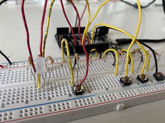
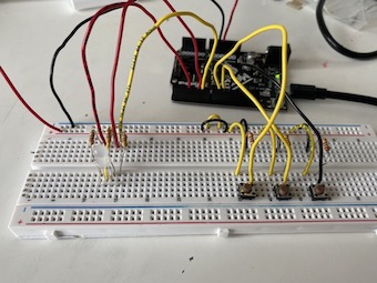
I first wanted to see if the for() loop was working, so I just uploaded the loop without any conditions (you can see the video for this trial below). I saw that the for() loop was working, so I wanted to improve my circuit a bit more. I took the second RGB LED from the kit and added it to my circuit. I created new outputs, and arranged the code according to the new circuit. The code was working but the lights of the RGB LEDs got really dim, and they started to work a bit slower. I thought that this might be because the 5V power source might not be quite enough, so I decided to try something different.
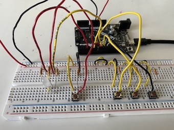
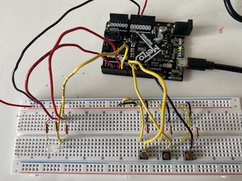
Since I already had the buttons to control the color of the RGB LED, I thought of adding one more button that would control the for() loop for the RGB. I changed the code and the circuit once again for this new design with four buttons. I first wrote the for() loop inside an if function but came across a few errors. Therefore, I decided to try and use the while() loop.
This time everything seemed to work correctly. The only thing that I should mention is the delay between the button presses and the RGB LED. The for() loop starts to run as soon as I press the respective button. However, it continues to finish the started loop, which is why it seems like there's a delay between me lifting my finger and the RGB LED turning off. Nevertheless, since the running for() loop isn't too long anyways, I decided to keep it as it is. With this final code, I was using if/else statements, a for() loop, and a while() loop. You can see the way that the for() loop is controlled via a button in the videos below as well. I was really happy with the final outcomes of this assignment.