ASSIGNMENTS
1. Design and prepare to print (i.e. slice) either (a) a component you need for your final project or (b) a small object that could not be (easily) made by subtractive methods. Upload your 3D model file (e.g. .f3z), STL file, and sliced gcode file to your documentation.
2. Scan something using a photogrammetry application, if you can get access to one.
Designing the Wind Turbine
For this assignment, I decided to start designing the wind turbine for my final project. Even though not every component is supposed to be 3D printed, I belive that it would be best if I print the blades of the turbine -one of the most crucial components of the design- via a 3D printer. After doing some research, I came to the conclusion that a savonius wind turbine with three blades would be the most efficient and sturdy option. I did some sketches to figure out how I could design a system that would be easy to assemble in real life. I saw designs on the internet where people just printed the whole wind turbine as a whole, but I didn't think that this would be really reliable since it would take a lot of time to be printed, and wouldn't be really reliable. Hence, I researched the mean sizes of AC Fan units to make the wind turbine at an appropriate size.
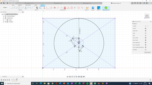
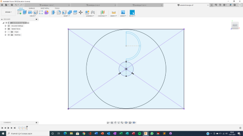
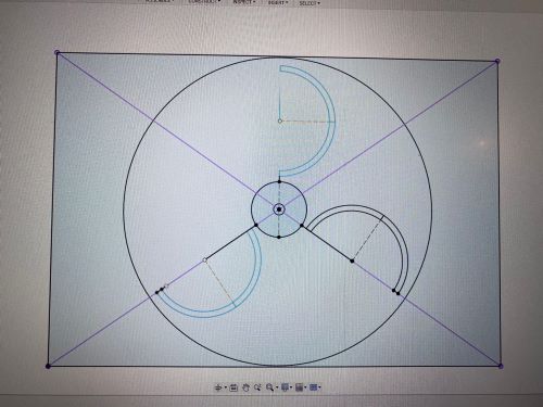
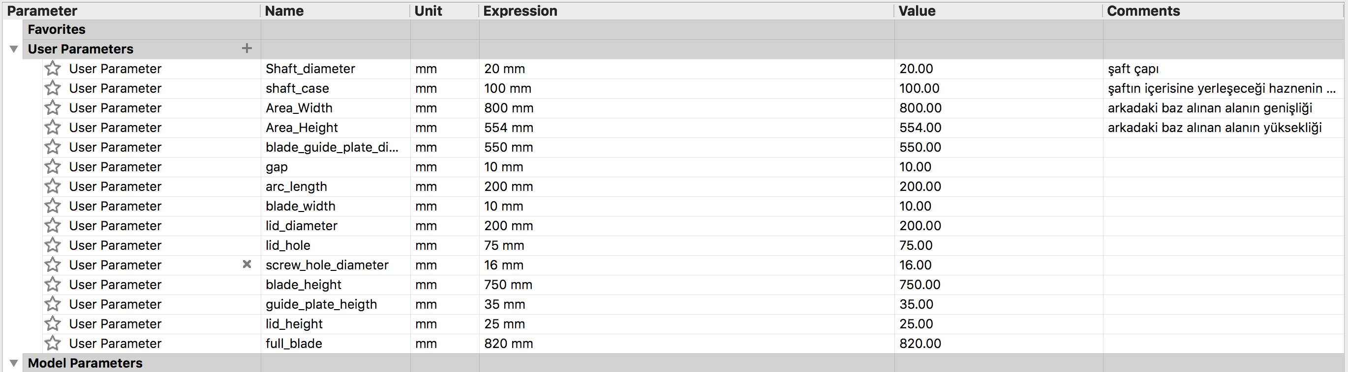
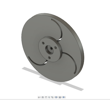
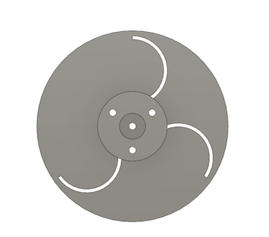
I created a rectengular sketch to see the size limit that I was working with. Afterwards, I created construction lines to get to the center of the rectengale, and sketched a circle inside the size limit. This would later be the guide plate that the blades would fit into. I looked at the sizes of motor shafts that were m-being manufactured, and sketched a circle in the middle for the shaft. Then, I started t add the shape of the blades to my design using a three point arc. Considering that I might need to change the measurements of my desig in the future, I used parameters for almost every aspect of my design.
Creating the Components
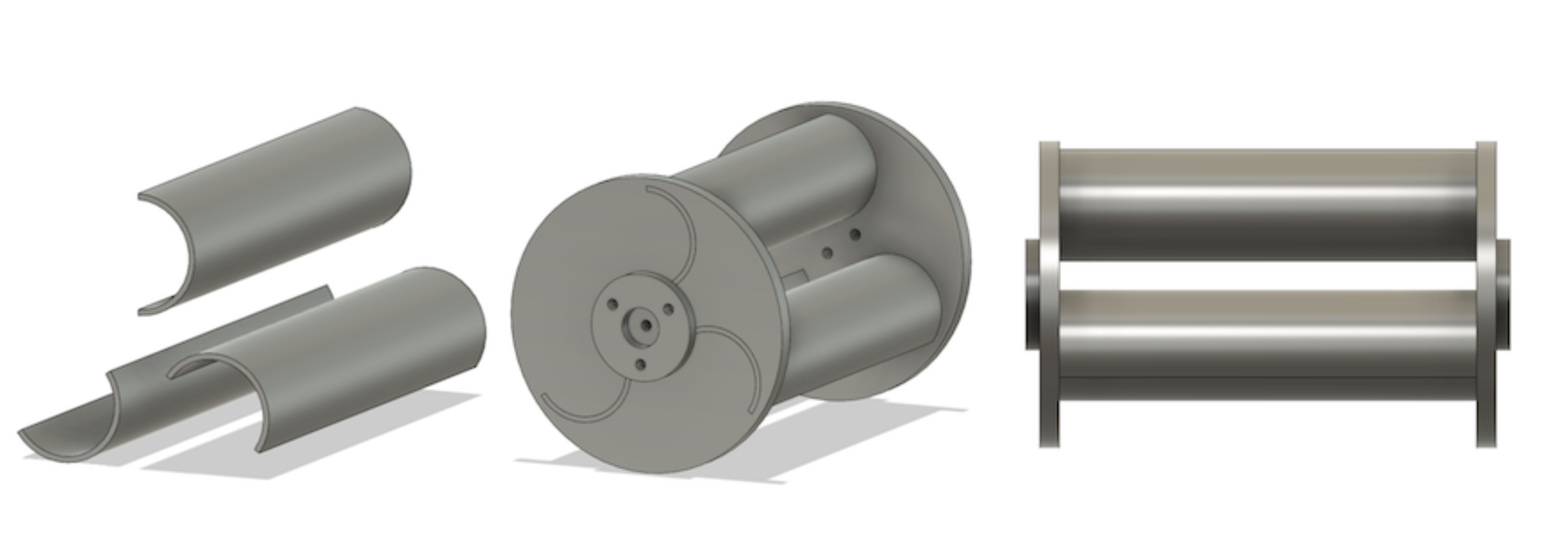
Now that the sketches were done, I could start creating the 3D components. By extruding the respective sections of the sketch, I created the guide plate, and the "lid" piece (I continued to use parameters while extruding the sketches). Then, I used the mirror command to create the components for the other end of the wind turbine. I arranged the distance between the guide plate according to the size of an average AC Fan unit. Afterwards, I just needed to create the blades. I used the project command to get the blade shapes from my first sketch, and then I used the extrude command to create the blades one by one. Afterwards, I attached the blades into their receptacles to form the shape of the whole wind turbine.
With the whole body formed, I realized that something was looking off with the design. I had to research some different wind turbine designs to figure out what I did wrong, and I realized that the directons of some of the blades were wrong. I copied the blade components and inverted them to get the right directions. However, I also needed to fix the guide plate according to these new directions. I filled up the previos blade holes by extruding the initial sketch. Then, I used to combine command to cut the guide plates according to the newly inverted blades (I used the blades as tools and kept them in the design).
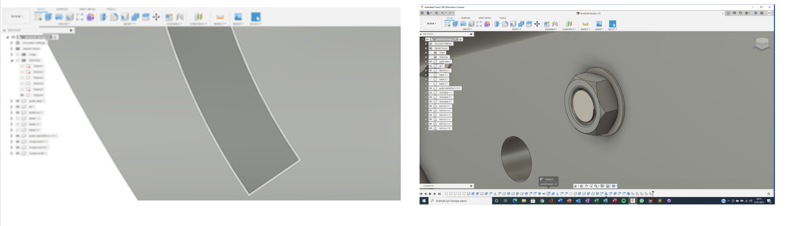
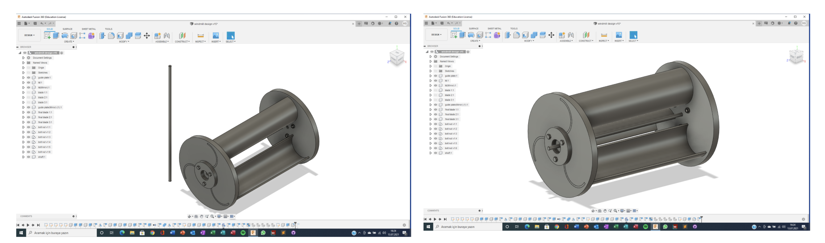
Now that everything was fixed, I could make some final touches to my design. I found a m16 bolt design from the internet and inserted it to my own design. I had to change the paramters to make the screw holes' diameter fit to the m16 bolt. I attached the screws to the holes that I initally created. I also sketched and extruded a motor shaft, and placed it such that it goes through the middle of the whole design.
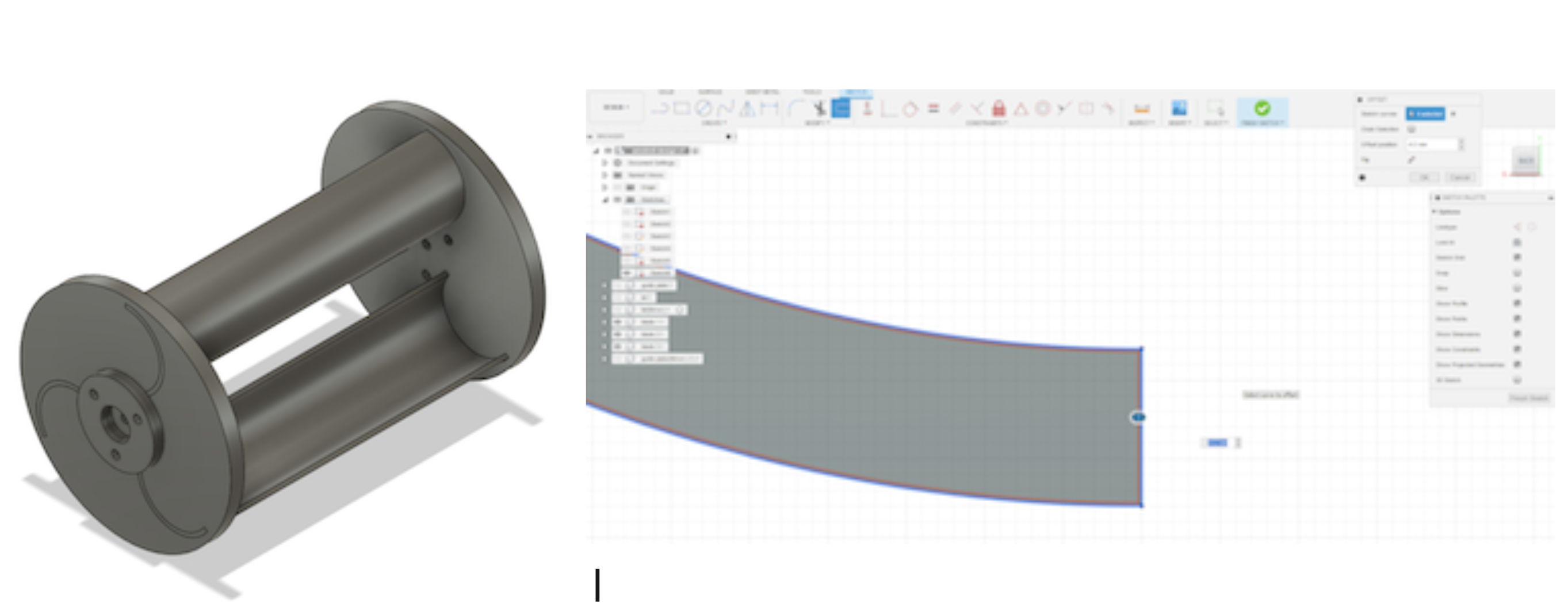
After finishing these components, I realized that the blades wouldn't be able to fit inside their holes in real life sice there simply wouldn't be any free space for them to move through. To fix this, I created sketches on the blades, and created an offest for the sketch so that the blades would be a little bit smaller than the holes. I extruded these new blades, and placed them inside the relative places. Finally, using the 'as-built joint' command, I created the required joints for my wind turbine design.
You can download this design here


Rendering & Animations
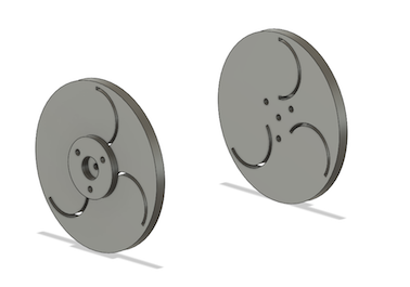
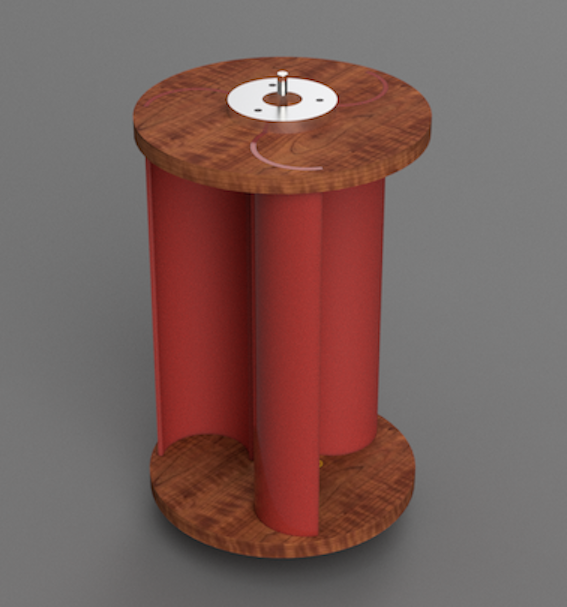
Now that my design was completed, I wanted to get a rendered image so that I can get a feel of how this wind turbine would look like in real life. Hence, I went into the Render Mode, and started going through several materials to find the right ones. I made the blades from plastic, and selected different kinds of steel/metal for the screws and the shaft. I also selected wood for the guide plate so that it would stick out in the design; however, I am not sure what material I am going to create this piece from. I might either print it from a 3D printer, or try to get a material cut according to my design via a CNC machine. After selecting all the materials, I started to adust the lighting and the background. I found the lighting mode that worked the best with my design, adusted the reflections, camera angle, and some other aspects of the render section. To be able to see the wind turbine from different angles, I copied and pasted the whole design, and turned it around. Finally, I started the rendering, and got the images that you can see on the left.
When the rendering was completed, I also wanted to test the joints that I created. I decided to also take videos of these since it would help others to better understand how my wind turbine design is goint to work. First of all, using the 'revolute' joint on the shaft, I made the whole turbine rotate as if there is wind blowing against its blades. Next, I wanted to display how the blades would be placed inside the guide plates. I used the 'slider' joints between the blades and the guide plate. To display this properly, I first created joint limits so that the blade would stop when it hits the lid on the other side of the guide plate. I closed the visibility of some other components so that it would be easier to see the moving blade. Then, using these limits, I animated the whole model, and got the animation of the blade being placed inside its respective hole on the guide plate.