ASSIGNMENTS
1. Work through a Fusion 360 tutorial, like this or some of these.
2. Select at least 2 components from the kit (or other simple household objects). Measure them using calipers, and model them in Fusion 360 (or other program). Create an assembly of multiple components, and document your work on your webpage.
3. Read: What is Electricity?, What is a Circuit?, Electric Power.
My Work
Throughout this lesson, we went over some of the tools inside the kit, learned about laser cutting, and practiced Fusion 360. The first thing that we talked about was the caliper. Even though I had used calipers before, I realized that there were many functionss of the caliper that I wasn't using properly. I learned about all of the different ways of measuring lengths with a caliper, and I'm sure that this will be really useful in the future. In addition, we talked about laser cutting.
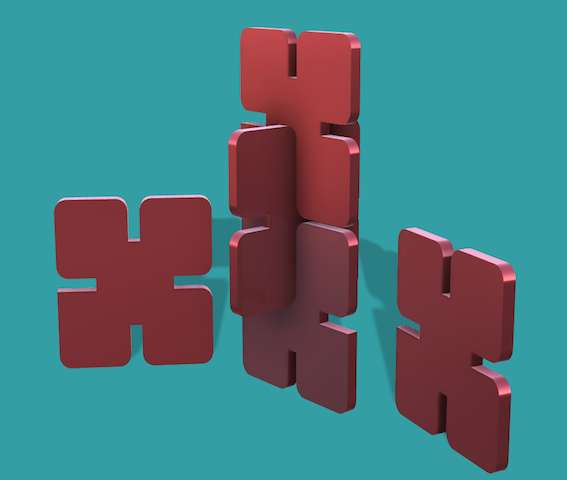
Even though I made 2D designs before, I had never used laser cutting, nor did research about it. Hence, I learned a lot of new things such as different laser cutters, the materials that can be used, and how different adjustments to the laser can alter the final product. We also talked about engraving and vinyl cutters. Finally, we went over a tutorial to practice using Fusion 360. I used Fusion 360 before; therefore, I was more comfortable with the software this time. One of the new things that I learned through this tutorial was how to properly use parameters. This made editing the design a lot more simple and smooth. [The image on the left is a rendered version of the final product form the tutorial that we went over in class].
Download the stl file for the Press-fit project
Computer Mouse
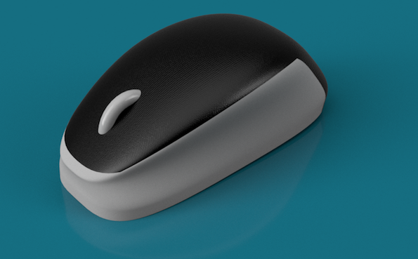
We needed to select components from the kit or household objects. I decided to model a computer mouse. Since this is an object that I regularly use, I thouıght that it would be fun to create a 3D model on Fusion 360. At first I inserted an image of the mouse to Fusion 360 to help me get the shape right. At first I thought about making a 2D sketch and extruding certain parts to create the shape of the mouse. However, I realized that it would be really hard to get the shape of the mouse right with a 2D sketch. Therefore, I decided to work on the 'Form' section of Fusion 360.
I clicked 'Create Form', and then inserted a box. After pulling and dragging different sides for some time, I managed to get the right shape. I created a new form to make the button at the top of the mouse, and merged these two together. I went back to the image, and made some final touches to the shape of the form, so that it resembles my own computer mouse. Finally, I went into Render mode, and changed the materials on the mouse. I also altered the background color and the lighting to get a nice photo. [The image on the right displays the final version of my computer mouse].
Download the stl file for the Computer Mouse
Tape Holder
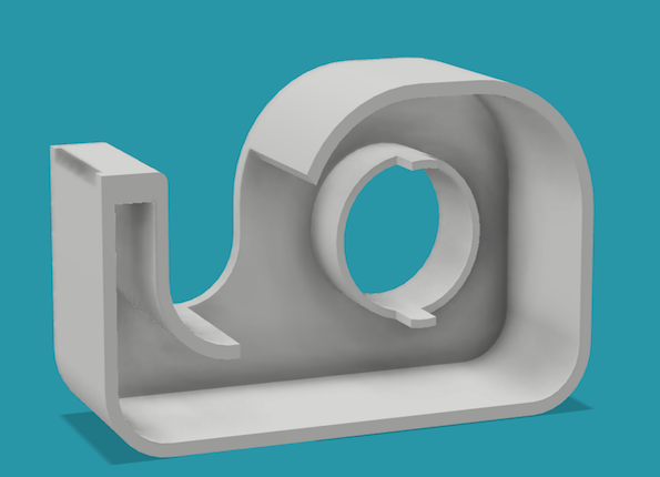
The next object that I chose to design was a tape holder. This was a relatively more simple design, but I wanted to work on a 2D sketch this time to create the final model. I measured the tape holder that I had with my caliper, and recorded the results. First, I did a 2D sketch of the outer body of my tape holder according to my previous measurememts. Then, I went over the same sketch and created a outer frame for the sketch, so that I would be able to only extrude the outer section of the sketch and leave the middle part empty. I extruded each part according to their own length and width.
Now that I had a 3D shape, I could start to add some more features. Using the 'Fillet' tool, I made some of the corners more smooth, so that the design looked more similar to the tape holder that I had. I also created a new sketch on the front part of the tape holder. I sketched a triangle and created a patter from it. Afterwards, I extruded the top section of these triangles inwards, in order to cut the tape holder. By doing so, I managed to form the sharp part of the tape holder which would cut the tape. Finally, I needed to add the the component that would hold the tape in place. I made a new circular 2D sketch to the inside of the tape holder, and once again extruded each section according to my measurements and merged this piece with the tape holder.
My tape holder was completed, and I went into Render mode in Fusion 360. I tried several different materials. Even though the real tape holder that I have was transparent, I saw that the transparent materails in Fusion 360 made it really hard to understand the features of this design. Therefore, I went with a more simple material, and changed the lighting as well. [The image on the left displays the final version of my tape holder].
Download the stl file for the Tape Holder
Assembly
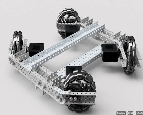
The final assignment was to create an assembly of multiple components. I have been working on VEX Robotics Competition for the past three years, and I wanted to create an assembly of a mechanism that I built last year but didn't get to design on Fusion 360. The machanism is called "X-Chassis" due to its unique shape. This was the chassis (drivetrain) of my previous robot, and was pretty fun to build.
The wheels that I used are called "Omni-Wheels". The reason that I chose these wheels for this mechanism is that these specific wheels can rotate both ways due to the small mobile pieces on their outer surface. With this formation, depending on which wheels you power, the chassis can both move in the regular way (directly front and back), and can also move sideways and diagonally without needing to turn. You can see an X-Chassis drive test (not the one that I built) here.
I downloaded the VEX Robotics Components form their website to began my assembly. I cut each metal to the required length by creating a 2D sketch and extruding them towards the inserted component. I saved each of these altered metal pieces seperately so that I can use them whenever I want. I used rigid joints to attach the screws and nuts to the metals. I used a 'Revolute' joint while attaching the shaft inside the motor so that it can rotate as it's supposed to.
After finishing one side of the chassis, I used the 'mirror' tool to create the other side. I attached the two sides together with several metals. I added some final pieces to the design so that it looks more like the real version that I built last year, and my assembly was completed. [The image on the right displays the final version of the X-Chassis that I assembled].
Download the stl file for the X-Chassis Assembly