ASSIGNMENTS
1. Make a circuit on a breadboard with components in the kit. Use a multimeter to measure the voltages in your circuit. Use Ohm's law to calculate the current through some part of the circuit.
2. Simulate your circuit.
3. Use the Microcontroller Analog in (ADC) to measure the voltage of a potentiometer, or other voltage-divider-based sensor.
4. Document your work and learning.
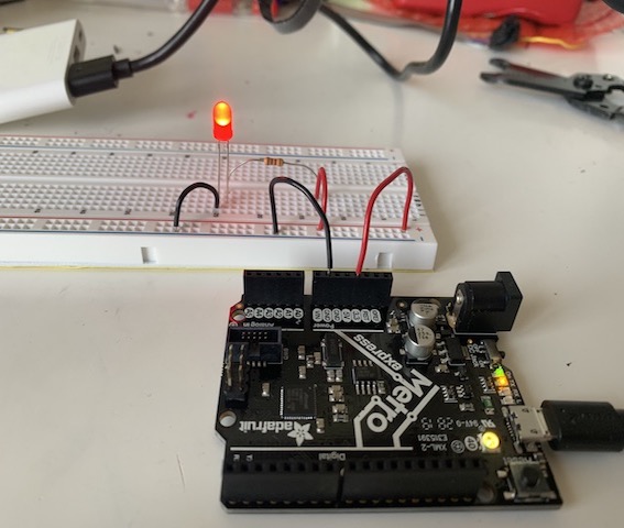
Simple LED Circuit
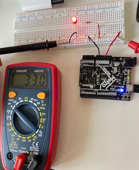
Even though I had studied electronic components and basic circuit before, I had never used microcontrollers, breadbords nor Arduino. Hence, these assignments were a bit challenging but I had a lot of fun while trying out different circuit designs. In this lesson, we first talked about what microcontrollers are, and got introduced to the basics of electronics. The image on the left displays the first circuit that we built in class to better understand how everything functions.
This was a more basic circuit, but it was a great opportunity for me to learn how to properly assemble a circuit on the breadboard. For this circuit, I used a red LED, a 100Ω resistor, some wires, and the Metro M0 Microcontroller. It took me some time to completely understand how the breadboard is connected, and to get used to cutting the wires. Adjusting the wire stripper was a bit of a challenge at first; however, I managed to get the hang of it after a few trial and errors. I needed need to upload any code to make this simple circuit work; I just plugged the metro board to my computer and got the LED to shine.
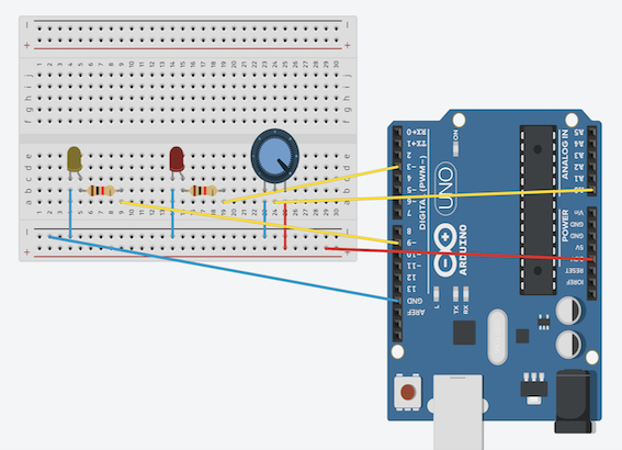
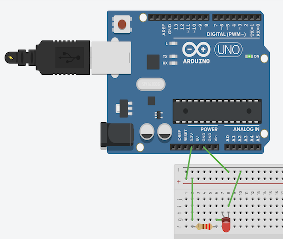
Tinkercad
Tinkercad was another program that we learned to use in class. I previously thought that Tinkercad was only a simpler 3D Design program, but learned that I can also use it simulate circuits. This was a really useful program for me since I never built circuits on breadboards before. The simulations allowed me to easily test circuit designs, and see how everything is supposed to be before building the circuit in real life. The image on the right is from Tinkercad, and it shows the simulation that I used for the aforementioned basic LED circuit. The simulation uses the exact components as the circuit that I built in class to give more accurate results. Simulating circuits in Tinkercad became a crucial step in my process of designing circuits on the breadborad.
Multimeter & Calculations
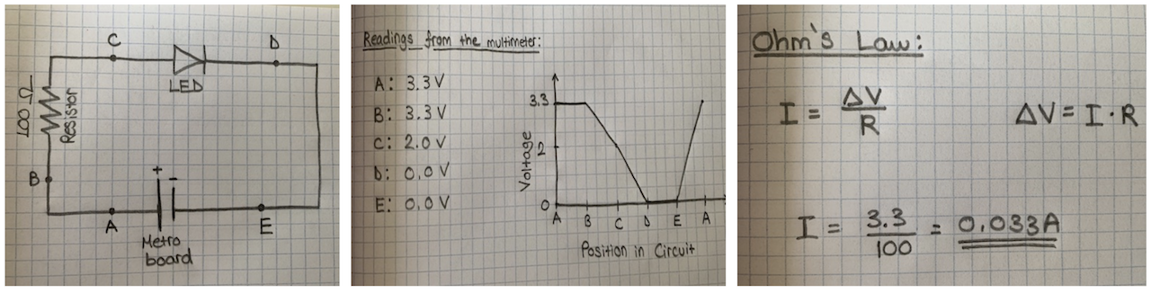
After building the circuit, it was time to use the multimeter and the formulas that we went over in class to read data from the circuit. Using the multimeter was quite easy and practical. I drew a schematic of this basic circuit on paper, and labelled five points (A to E) to read data from. I sketched the resistor, the LED, amd the Metro board (as a power source) on my schematic. I used the multimeter to record the potential differenve (voltage) at these specific points, and sketched a Voltage vs. Position in Circuit graph to properly display the results. Afterwards, I used the Ohm's Law to calculate the current going through my circuit. This circuit analysis was helpful for understanding how the theoretical and physical aspects of this subject fits together.You can see a photo of my measurements with the multimeter, the graphs, and the calculations below.
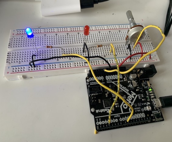
Double LED & Potentiometer Circuit
For the assignment, I needed to build a new circuit. For this circuit, I decided to try and use the potentiometer for a bit more advanced design. After some research, I found a design which controls two LEDs with a potentiometer. Fİrst of all, I started to build the circuit in Tinkercad to make sure that everything would work as desired. While simulating this design, I had some problems with lighting up the second LED. After trying it out several times in Tinkercad, I decided to build the circuit in real life and test it that way. I stripped some new wires for this design, and built it with some help from the template that I found.
For this circuit, I also needed to write a code to make it work as I wanted. I had uploaded Arduino IDE in class, so I just inserted the code to the Arduino software. Now I needed to upload the code to my Metro M0 Microcontroller. After downloading several files, I managed to matched the program with my Metro microcontroller. The program gave some errors at first; afterwards, I realized that the problem was occuring because of the selected port, and I figured out how to arrange the right port before uploading codes. Everything was working as it was supposed to, and I uploaded the code to the microcontroller.
However, when I tried to power the circuit, I came across a problem similar to the one on Tinkercad. While the red LED was lighting up, the other was quite dim. I played around with the circuit for a while, changing the directions of some components, attaching new wires, and trying to figure out the problem. After some while, I realized that different colored LEDs had different brightnesses with the same power source. I saw that the my blue LED was lighting up properşy next to the red one, so I decided to use that one in the final circuit. You can see the circuit, my simulation on Tinkercad, and the code on the right. After finishing design, I changed several aspects of the circuit and the code to fully understand how different aspects of circuits and the code worked. This was a really fun assignment to work on.