ASSIGNMENTS
1. Use a sensor from the kit to measure a physical quantity with your microcontroller. Calibrate your sensor (describe the range between its min and max values, and whether you can control this range). Show data in the form of a table or graph.
2. Do the same as (1) with a sensor you have fabricated yourself using copper tape, aluminum foil, Velostat, etc.
Using the Thermistor
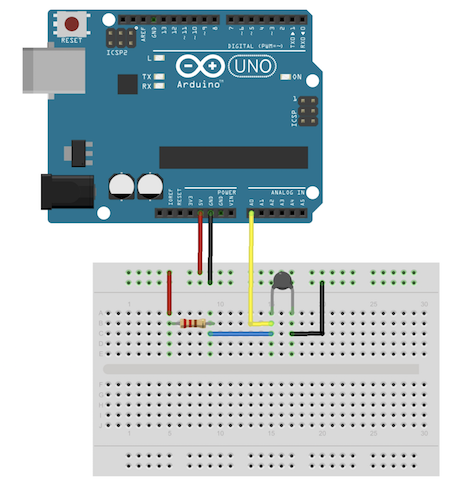
For this assignment, I wanted to try and use the thermistor. I had no prior knowledge about using sensors such as a thermistor; hence I started doing some research. After looking at some different designs, I decided to use the schemtaic on this website. You can see the circuit design from Tinkercad on the left. For this circuit, I cut and stripped a few new wires. It was quite easy to build the circuit. Now, I needed a code to get the thermistor to work.
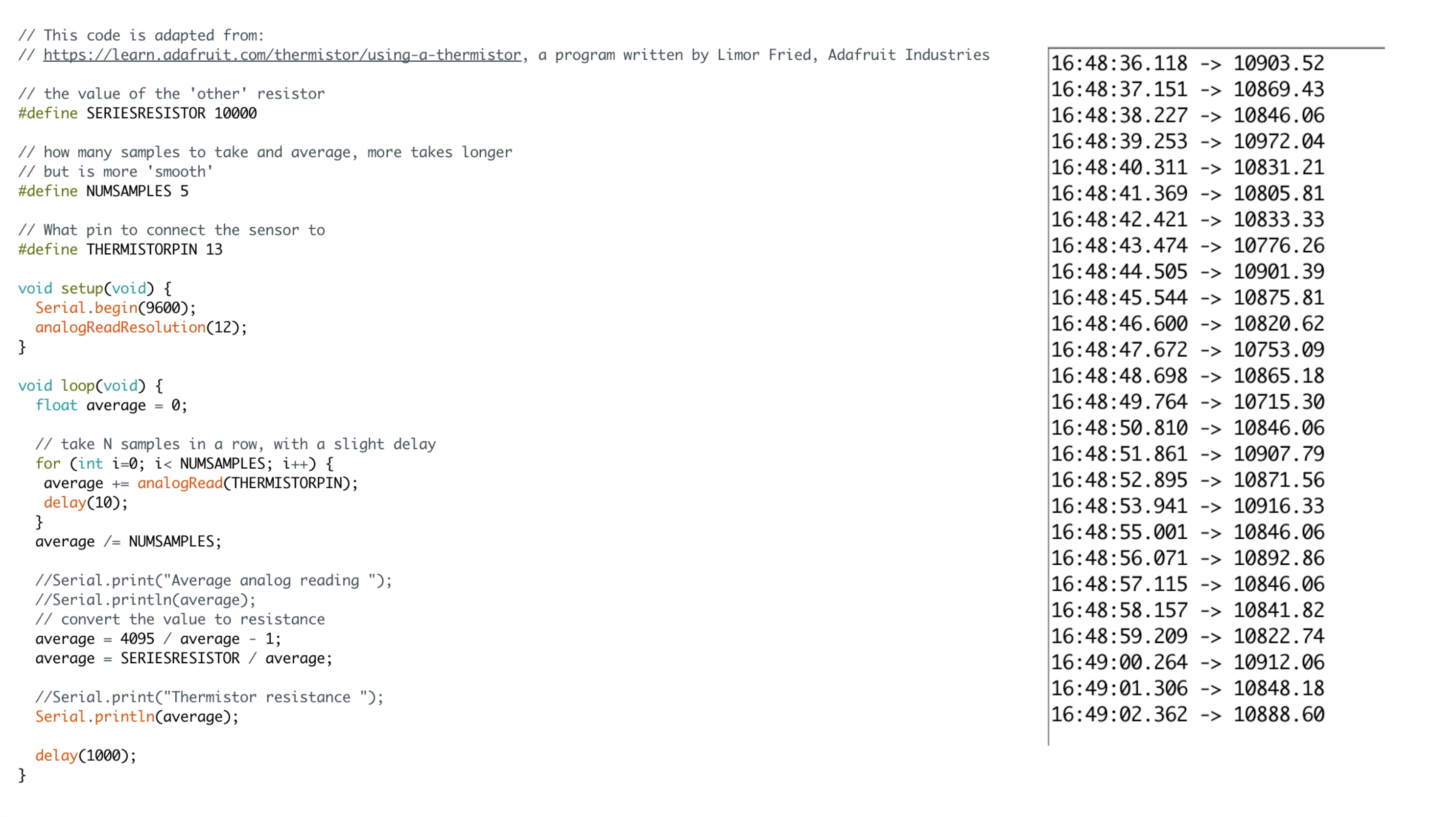
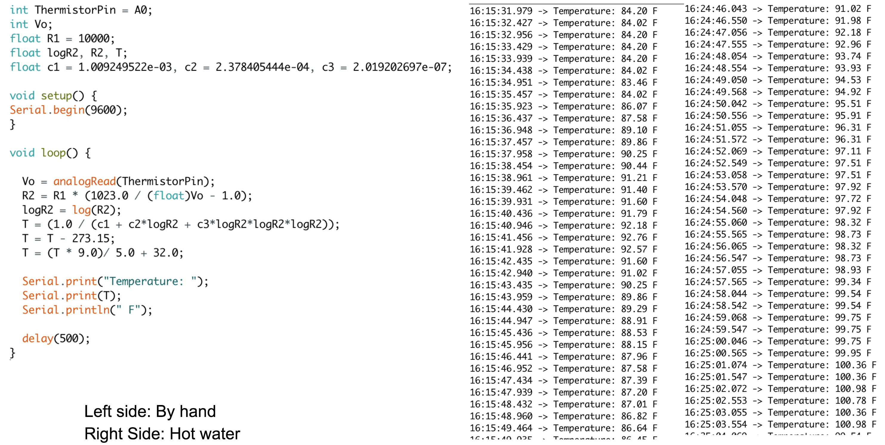
I came across this Arduino code which was written to get readings from the thermistor. I uploaded the code to my Metro Board but couldn't get it to work. After going through the code for a while, I realized that I had forgotten to change the pin that the thermistor was connected to. After fixing this mistake from the code, I was able to get some readings. (You can see the code that I used and the Serial Monitor page below). However, the values that I was getting were not transferred to real temperature units. I wanted my code to convert the results, so I started to search for a different code.
Converting the Values & Different Setups
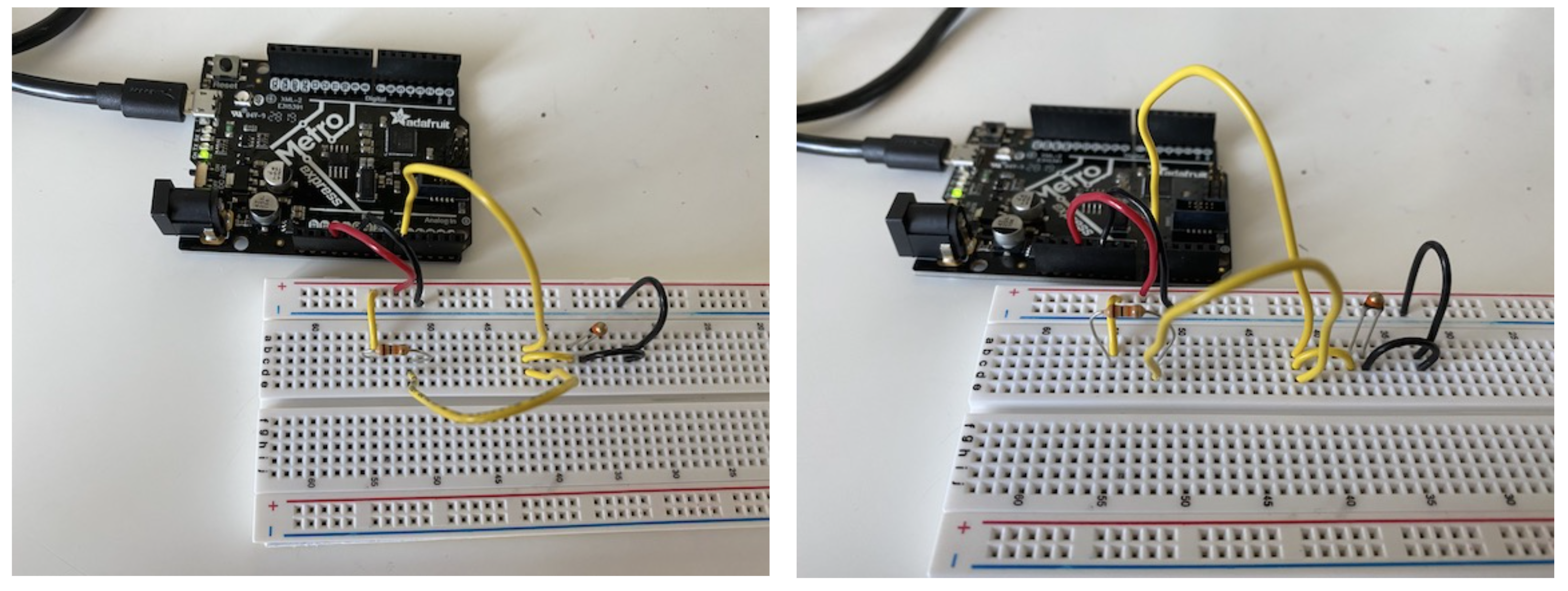
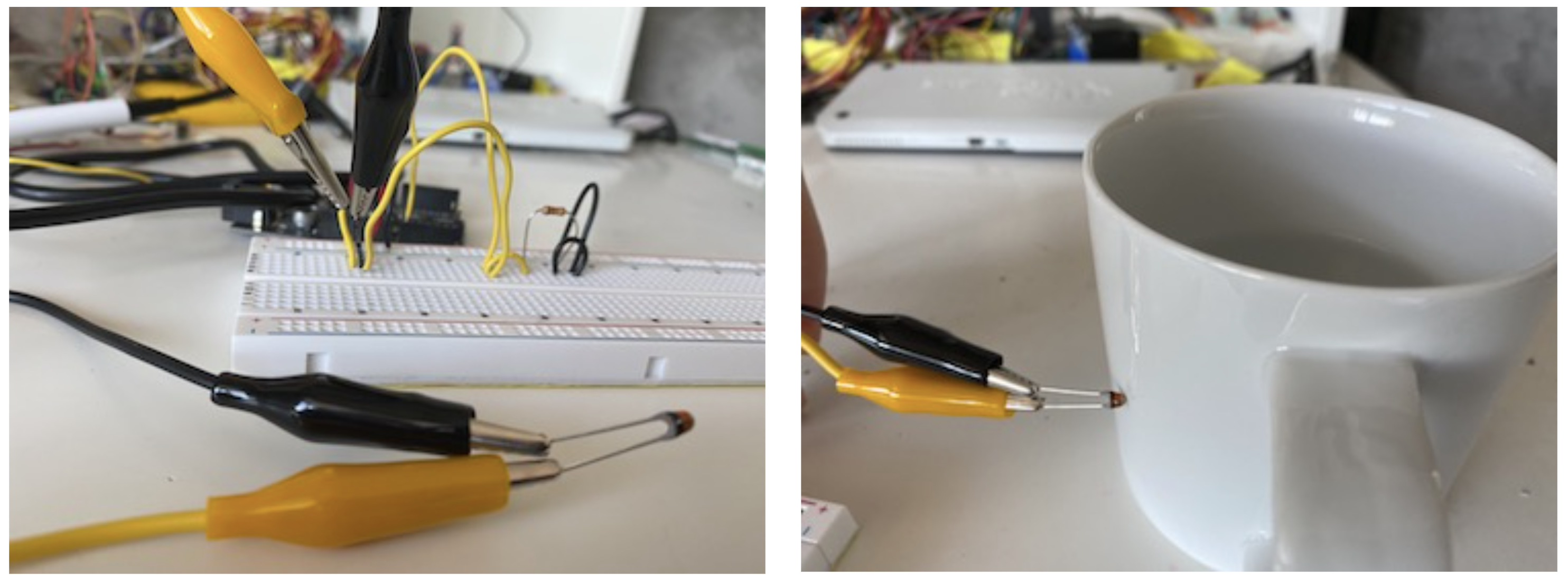
I found a different code (from this website) that would convert the values to Fahrenheit. I copied and pasted this code, and uploaded it to my Metro Board after arranging the pins according to the circuit that I had built. This seemed to work as I wanted. I was now converting the readings to Fahrenheit. I tried holding the thermistor to see how to data would change. However, there seemed to be a slight issue. The temperature was falling when I held the thermistor insted of rising. I wenth through the code to see if there is anything that I can fix. I wasn't able to fix this problem from the code, so I decided to do some more research to see if anyone else had a similar problem. On a forum, someone mentioned that switching the components might help with this problem. It was worth a try, so I altered the circuit a little bit and switched the places of the resistor and the thermistor. This seemed to work, and the temperature was now increasing as I held onto the thermistor. I transferred the readings from Fahrenheit to Celcius via an online converter. The readings were surprisingly pretty close to the actual temperature of the weather.
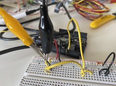
I wanted to also try the thermistor with more inetnse temperatures. I got the idea of pouring boiled water in a glass, and measuring it with the thermistor. However, I was scared that I would damage the circuit with the hot water. From Dan's Documentation, I got the idea of using alligator clips. So I once again slightly changed the circuit design and attached the thermistor to alligator clips. I touched the thermistor to the hot glass, and saw that the readings increased more than when I was just touching the thermistor. This was a quite fun circuit design to play around with. (You can see the codes, readings, and the circuits below)...


Self Fabricated Sensor
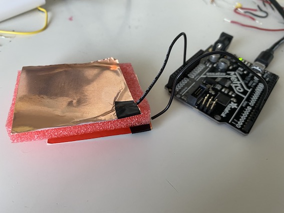
For the self fabricated sensor, I decided to try working with a "force sensor". I took the two copper electrodes and attached on to pin4 and the other to A0 port of my Metro Board. Then, I took a foam piece and placed it in between the two copper sheets. Afterwards, I downloaded the Arduino sketch for tx_rx Single measurement from the course website, and uploaded the code to my Metro Board. To see if the code was working, I checked the Serial Monitor as I pressed on the top copper sheet. I saw that the values were decreasing as I pressed on the copper sheet. After seeing that this design was functioning, I decided to try and use this as a switch to power a LED.
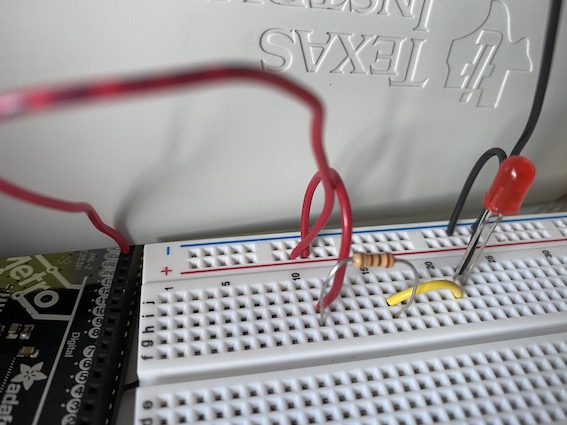
For this purpose, I built a simple LED circuit on the breadboard and connected it to the Metro Board. I simply used one red Led (since I observed that it was easier to light up the red LED in previous assignments) and a 100Ω resistor. After building the LED circuit, I needed to write a code to power this design. I thought that a basic if/else function would do the job. I checked the readings from the Serial Monitor to see the range of the values. I saw that the values rose almost above 100 when I stopped presasing, and fell below 50 when I pressed on the top copper sheet. Hence, I chose the approximate value of 50 to be the threshold of my if/else function. After testing the code for the first time, I observed that 50 was a bit too high, and it prevented the LED from lighting up as soon as I pressed the copper sheets. Therefore, I decreased the threshold of my loop function to 20, and this seemed to work better.
Even though this worked the first few times, it started to malfunction after a while. I believe that this was due to the thickness of the foam that I placed in between. my guess is that the foam was too thick, and caused the copper sheets to disconnect from one another, causing me to read 0 in the Serial Monitor. Thus, I had to take out the foam piece, and just used the copper sheets. This turned into more of a distance sensor as I was moving one copper sheet up and down. Nevertheless, my design started to wore more effectively this way. The one last thing that I realized that there was a delay between my movements and the brightness of the LED, I am not sure if this is completely normal but I will try to play around with this design a bit more to see if I can fix that as well.