ASSIGNMENTS
Make and document either (a) a kinetic sculpture or (b) a quick prototype of a possible final project. This should integrate an electronic circuit with physical components. In addition to components in the kit, feel free to use materials you find around the house (cardboard, toothpicks, coat hangers, tape and glue, etc.).
1. Include circuitry to move your sculpture/prototype.
2. Control the sculpture with a circuit on a breadboard that uses components in the kit (e.g., resistors, potentiometer). Use a multimeter to measure the voltages in your circuit. Use Ohm's law to calculate current through the circuit.
3. Use the Microcontroller Analog in (ADC) to measure the voltage of a potentiometer, or other voltage-divider-based sensor.
4. (Optional) Use tools like TinkerCAD to simulate your circuit and/or tools like Fusion 360 to design and simulate your mechanism.
5. Document your work and learning. Include at least one video/gif of your sculpture.
Design Process
For this assignment, I wanted to build a functional mechanism that I could utilize with the motors that we used in class. I had a lot of eraser left overs on my desk, and this gave me the idea of building a cleaning robot that would collect these left overs. I had some metal pieces and gears that were lying around due to a previous competition that I attended to, and I decided that it would be a good idea to use these materials.
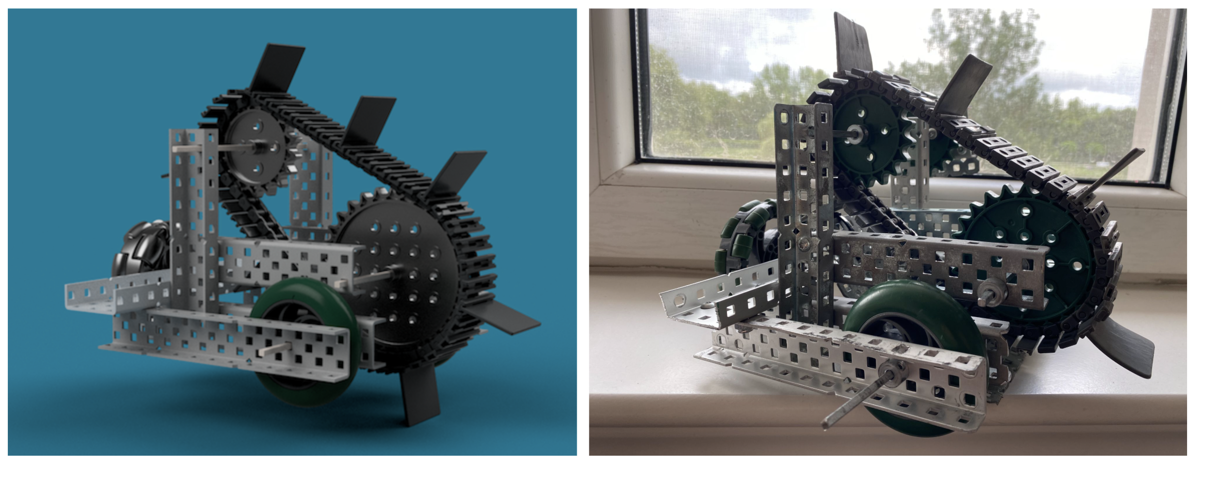
After making some sketches, I came up with a final idea. I decided to build this design in Fusion 360 to make sure that everything would fit together. I downloaded a library for the components that I was using, and inserted them to my own design in order to build the final assembly. I used rigid joints to attach the metal pieces, and used revolute joints for the shafts that held the wheels and the sprockets. I had to cut some metals in Fusion 360 to make sure that the robot would not be too large.
After completing the overall assembly, I just needed to attach the conveyor-belt that would collect the eraser left overs. I inserted one conveyor piece to my design, and attached it on one of the sprockets. Then, I created a sketch along the two sprockets to form the shape that the conveyor-belt would be in when fully connected. Afterwards, I used a "pattern along path" command, to form the whole conveyor-belt. Finally, I attached several plastic pieces to the conveyor-belt to form the structure that would brush in the eraser left overs
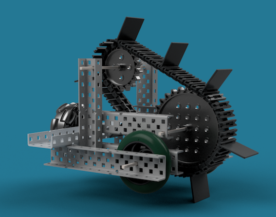
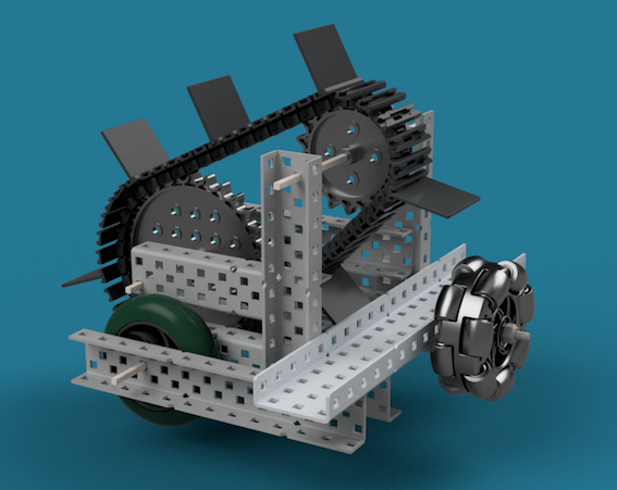
You can see my final design on the left. To finish things off, I created a rendered image of my assembly by adjusting some of the background colors, and the lighting. I also created a short video in the Animation section of Fusion 360. Now, I was ready to build the real mechanism.
Download the final design's STL file
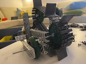
Building the Assembly
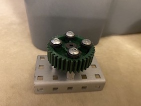
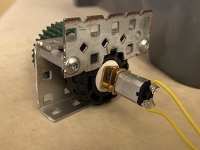
It was easy to build the mechanism using the 3D design that I previosly assembled. However, the first thing that I needed to figure out was how to connect the DC motor to the components that I was using. To do this, I decided to build an external component that would be the linkage between the DC motor and the gears that I'm using. I attached the motor to the LEGO wheel that we had inside the kit. Then, I found a metal piece that could hold the wheel inside. I found a metal at the size that I was looking for, and squeezed the wheel inside. I placed screws under the wheel, and attached a gear to the other end of the metal. This would be the part that would connect to the mechanism that I was about to build (I later changed the gear with a sprocket as well). Even though the small metal piece was holding the LEGO wheel effectively, I decided to build a "cage" for it so that it wouldn't move when I start powering the motor. I got a flat metal piece, and cut it so that it would not prevent the motor from rotating with the wheel. I attached this metal from the other side of the wheel, and trapped it inside. This component would allow me to link the DC motor to the materials that I was using.
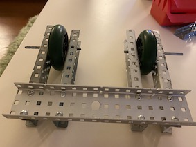
I decided to start building the mechanism with the chassis. I took four metal pieces and cut them according to the lengths that I determined on Fusion 360. Afterwards, I attached these four metal pieces together with a larger metal that I placed on top. I used the screws and nylock nuts that I had to build a firm structure. With the chassis built, I could now place the wheels. I had two small wheels, and decided to attach one on both side. I placed shafts at the front of the chassis, and placed the wheels between the two metal pieces on both sides. I fixed the wheels to their desired place and prevented the shaft from moving via setscrews. It was a bit hard to keep the wheels in the middle, but I managed to keep them there by placing a few plastic spacers on the shaft. To keep the chassis balanced, I needed one more wheel. However, there weren't any place in the front, so I started to attach it to the back just as I did on Fusion 360. For this wheel I used a loosely tightened screw instead of a shaft since there was only one side that I could attach the wheel to. I used a differen type of wheel at theback to make sure I didn't prevent any type of movement of the drive-train.
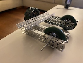
Next, I needed some metals to build the platform that would hold the sprockets in place. I once again cut a few metals, and attached these metals to the chassis according to my 3D Design. After making sure that everything was stable, I could begin attaching the sprockets to form the conveyor-belt. I placed two shafts between the metals that I just attached, and placed different sized sprockets on these shafts, fixing everything with setscrews. I had to make sure that thw sprockets on the back and the front were completelşy alligned. Then, I got the required number of conveyor-belt pieces, and built the full belt by attaching them together. I also needed to place the plastic pieces on these pieces to create the brushing effect. I attached this belt on the sprockets, and everything from my Fusion 360 Design were built.
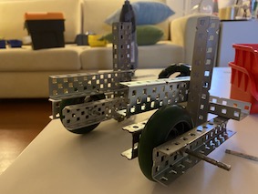
Now, I needed to make some final touches. I wanted to build a simple piece inside the chassis to store the eraser left overs that the device would collect. I couldn't add this on Fusion 360, since I was planning to bend some pieces and didn't know the angles for sure. I took a flat aluminum piece and bent it according to the chassis, making the end part parallel to the ground. I wanted this to be an adjustable component to be able to use the cleaning robot on different surfaces. So instead of using screws, I attached this bent metal via zip-ties, allowing this metal to slightly move up and down according to the ground level.
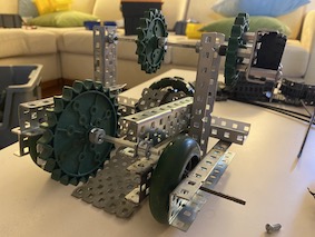
The last thing that I needed to do was attaching the motor to this assembly. I took the "motor cage" that I built initially, and attached the sprocket on it to the top shaft. The idea behind this design was; when the motor was powered it would start rotating the LEGO wheel that it was attached to. The wheel would then continue to rotate the sprocket that it was attached to due to the "cage" that I designed. This turning sprocket would also rotate the top shaft, causing the conveyor-belt to continously rotate inwards as long as the motor as working.
Getting the Motor to Work
Now that my mechanism was completely built, I needed to work on powering the motor the get the conveyor-belt to rotate. I placed the small DC motor to the wheel on the side of the mechanism. Using the code that we worked on last lesson, I started to rotate the motor. I tried different example codes from the website to see how the motor's rotation would move the mechanism. However, there was a big problem. The motor was rotating inside the wheel, and not rotating the system probably because it could not supply enough torque. After playing around with the component that I attached to mtor to, I realized that this was not going to work. Hence, I decided to try some new solutions.
I decided to build a gear reduction to increase the torque of the motor. I once again switched the sprocket attached to the motor with a small gear. Then, I transferred the motor's rotation from a small gear to a larger gear in order to increase the torque. Regardless of what I did, the conveyor-belt would not rotate (I could rotate it by hand) because the friction was probably still too much for the DC motor to rotate on its own. I though of trying working with different power sources to see if that would fix my problem. I took the batteries from the kit, and attached my Metro board to these batteries instead of my computer. This was still not enough.
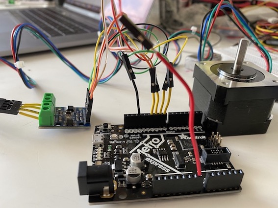
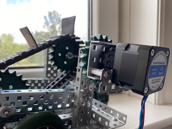
I had one last idea... I thought of using the stepper motor hoping that it might be able to supply a greater torque. However, I had no idea how to use stepper motors. So I did a lot of research, watched many tutorials, and went through the week 8 page. At first I tried building a circuit with the Stepper driver, but couldn't get it to work. So following the week 8 tutorial, I built a different circuit. The circuit was fully connected so I uploaded the demo code to Arduino. I could feel the stepper motor trying to rotate with really small movements, but it wouldn't continously rotate. I tried many different codes, but couldn't manage to get the motor to fully rotate. I was out of ideas and time, so just had to leave it at that.
Things to Consider
It was very disappointhing that I couldn't get my mechanism to move. Even though I felt like I did a good job with the design and building aspects of the structure, and tried out several different circuits, I took a risk by working with heavier components such as metals and gears instead of pieces like cardboard, paper, etc. Hence, I can clearly say that I learned my lesson. I will try to build a different kinetic structure with ligheter compononets as soon as I have some extra time on my hands. But until then, here's a video of me rotating the shaft via hand to display how it would have worked...