ASSIGNMENTS
1. Send data to a computer and display results with code you've written (e.g., visualization of sensor data, browser-based game with microcontroller-based interactions, etc.)
2. Document progress on your final project. Consolidate your final project updates to a single "process" page. Optionally, create an additional concise "finished product" page. Plan on creating a 1-minute demo video for your final project. Here are some examples.
3. Find a pattern to cast and a ventilated space for class on Tuesday. Do not handle the molding and casting supplies without wearing gloves.

Talking to your browser over USB (Chrome)
For this week's assignment I decided to go with the "Talking to your browser over USB (Chrome)" option. Not a lot of programming is required for my final project, and therefore I wouldn't be able to really use any of the given assignment options for my wind turbine. Hence, I thought that it would be best if I don't waste too much time on computer porgramming, but I still wanted to experiment with it.
I followed the given tutorial , and after working a bit on the given codes I was able to get it to work. I built a simple circuit with a potentiometer, and connected it to my Metro Board. Then I created the index.html, sketch.js, and serial.js files as explained in the tutorial. I didn't spend too much time on computer programming, but a lot of detailed explanation can be found on this subject on the Class:11 Page.
Working on my Final Project
I continued to work on my final project this week. I had printed the blades, and was just about to start 3D printing the Guide Plates. The Lid pieces that I manufactured seemed a bit too thick after seeing them in real life. This wasn't a problem since I had used a light material, but I was afraid that a too thick Guide Plate could increase the weight as well.
I wanted this design to be as light as possible for it to be able to freely rotate, but it needed to be sturdy as well. Sometimes it got hard for me to visualize what the final product would look like from Fusion 360 (which is what happened with the Lid pieces). For this purpose, I decided to create a prototype for the Guide Plate. However, I didn't have enough supplies to 3D print prototypes; therefore, I had to use different materials to form a Guide Plate.
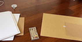
I bought several cardboards, and wooden boards to work with. I decided to use these materials since they would allow me to create a light, and durable piece. I went to my Guide Plate design on Fusion 360, and took a screenshot from the top. I printed this image in the appropriate proportions.
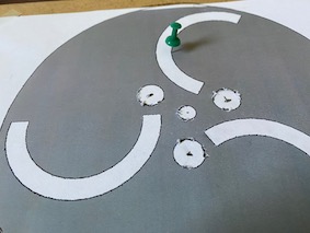
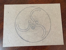
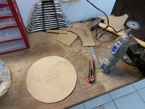
Then, I sticked the image on one of the wooden boards, and traced its lines with a push pin to create the pattern on the board. Afterwards, I took off the image, and sketched the Guide Plate on the board by following the traces of the push pin. I made sure that everything was in the same size as my design while sketching the Guide Plate. Now, I needed to cut out this Guide Plate.
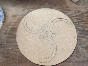
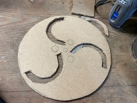
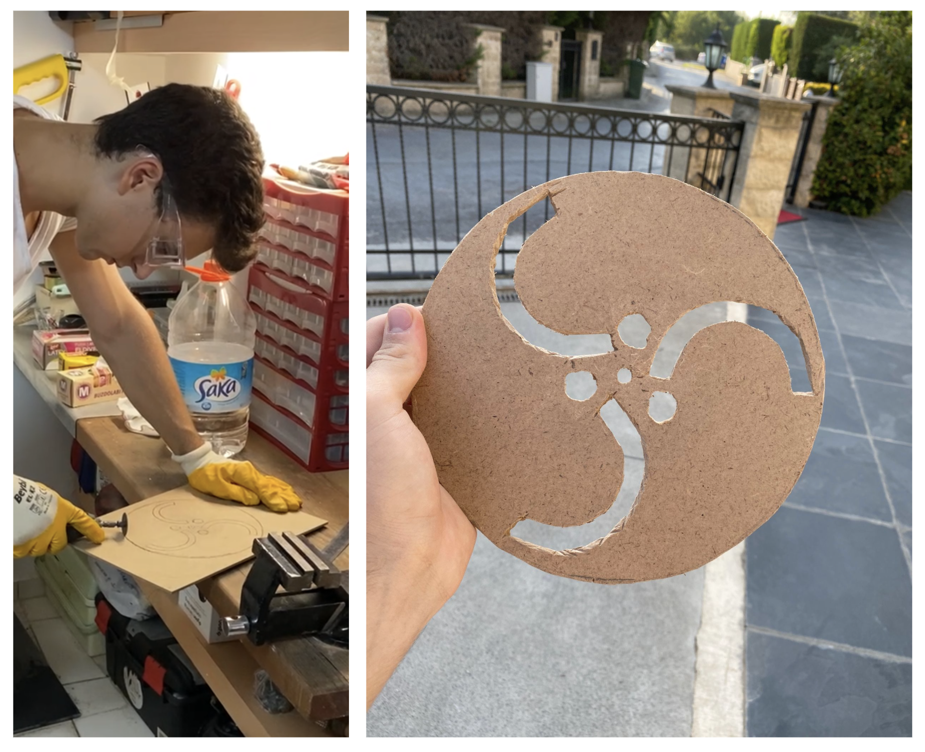
First, I tried using a utility knife, but it wasn't sharp/strong enough to cut the wooden board. So I decided to use a Dremel that I had (You can find a similar one here). It was hard to cut the circular shapes with this tool, but I managed to properly cut it after a long time of trying to follow the sketch. I got used to cutting these shapes along the way, so it was easier to cut the final parts.
For the holes, I used a drill. I took the m16 screws that I ordered, and used them to make sure that the holes that I drilled were the correct size. Now, my prototype Guide Plate was ready.
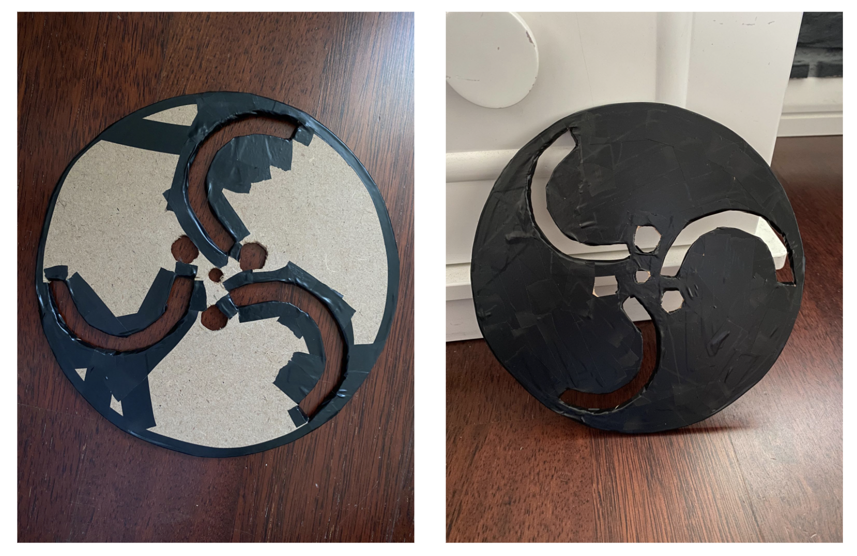
After finishing the Guide Plate, I used some sandpaper to fix the sides of the wooden board. I wanted it to be completely safe, so I used some electrical tape to cover all of the sides of the Guide Plate. I really liked the final product, and was excited to see what the 3D printed one would look like. I used my calipers to measure the thickness of this prototype Guide Plate. It turned out to be 0.8cm. My original design in Fusion 360 was 1.5 cm thick, and after seeing this prototype, I decided to decrease the Guide Plate's thickness to 1cm.